The Revit Interface…
- Does not have a command prompt
- Designed intentionally for architects and engineers
- Offers many choices and options behind each command
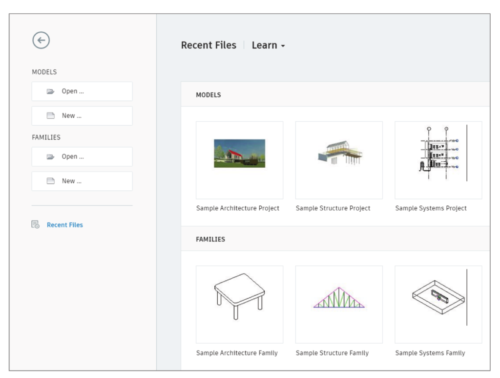
The Recent Files Window
- User can choose to open a new model or work on a pre-existing model.
- By selecting ‘New Project’ and choosing Architectural Template you can work on a pre-existing template file or create a new template file.
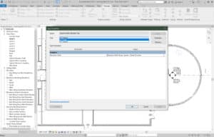
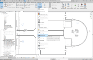
It is a three-step process:
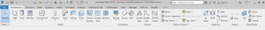
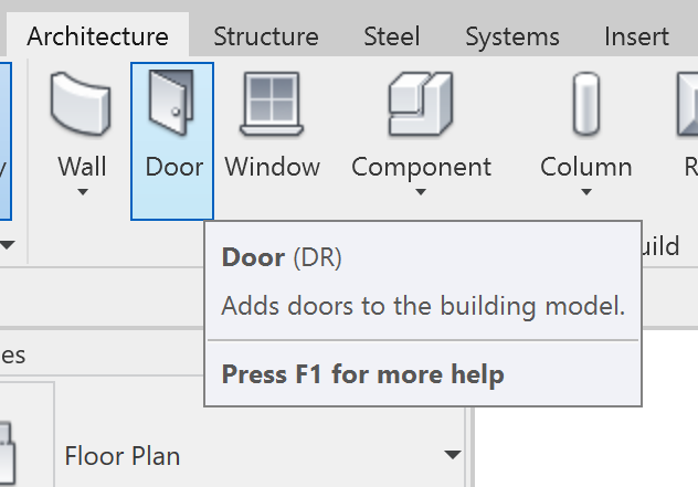
- Start the Command | At the top of the Revit window is the Ribbon with different tabs. Each tab has a panel.
- Choose an Option | After something from this panel is chosen, Revit adds an extra tab to the Ribbon with additional choices. It may also at times add more options below the Ribbon.
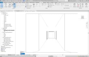
- Place item | After choices are made from the Ribbon and the Options bar, the object can then be placed into the View window. The View Window is the large area that takes up most of the Revit interface.
![]()
The Quick Access Toolbar is the the toolbar above the Ribbon.
- It hold the most popular commands
- You can add more commands to this toolbar:
- Right-click an icon
- Click Add To Quick Access Toolbar
- To the left of the toolbar is the Revit Application Icon
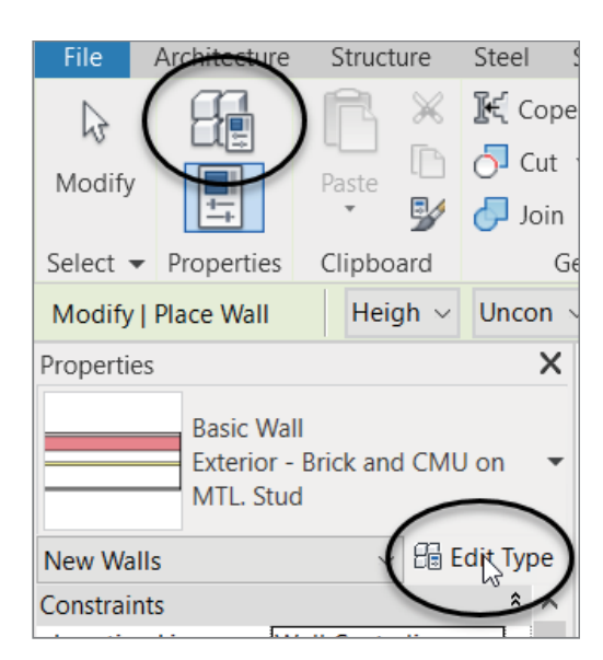
There are 2: Instance Properties and Type Properties
- Instance Properties – Are seen immediately in the Properties dialog when an item is placed or is selected
- Type Properties – Alter every item of that type in the model
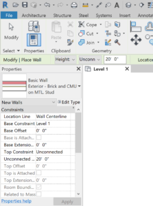
If an item is selected it shows the instance properties, if not the Properties Dialog shows the properties of the current view.
An Instance Property or parameter can be edited immediately and only changes the object selected in the model. This makes sense as not everything is built the same in the real world.

- Changes every item of that type in the entire model
- They are accessed by clicking on Edit Type in the Properties Dialog
- Example: A new wall type can be created by clicking the Duplicate Button or a wall type properties can be edited. (Be careful editing a type property without duplicating the type!)
There are 2 ways to select an object:
- Using a Cross-Window
- Using a Box
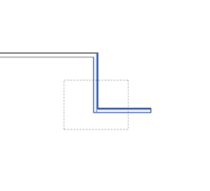
A Crossing Window is used to select objects by placing a window that crosses through the objects that need to be selected. Crossing Windows start from the right and end on the left. A crossing window is represented by dashed-lines.
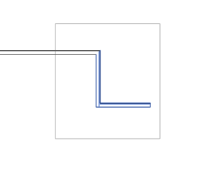
A Box is used to select all the objects that are inside the box. This selection method is useful when selecting items that pass through larger objects that you do not want to be selected. A Box starts from the left and ends on the right. A box is represented though a continuous line.
The View Control Bar is located at the bottom left of the view window.
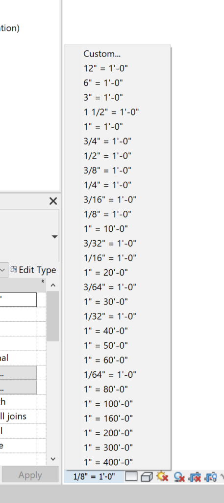
Scale – Allows you to change the scale of the view. Revit will scale annotations and symbols accordingly.
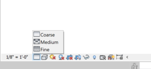
Detail – Allows you to view a model at different qualities:
- Coars
- Medium
- Fine
This allows you to control the amount of detail in a specific view. This isn’t temporary, this is how Revit will plot the view.
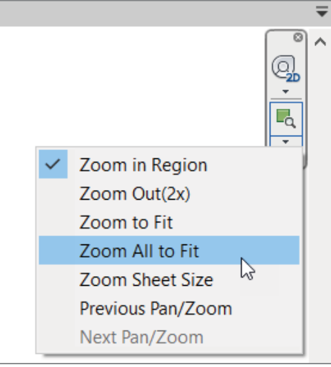
It is at the Upper Right corner of the window.
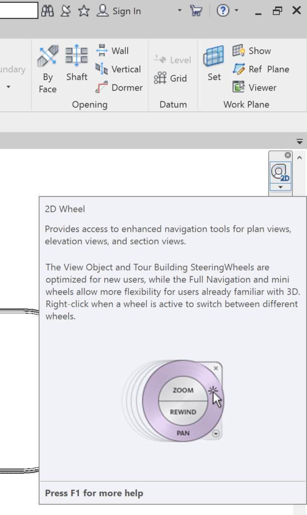
The Steering Wheel allows users to zoom, rewind, and pan on the drawing. It can be found within the Navigation Bar by clicking the 2D Wheel icon.
The Steering Wheel has a couple options:
Pan – Allows users to pan on their view
Zoom – Allows users to Zoom into the view
Rewind – Allows users to find older views
They are located within the Navigation Bar.
If you are working with a physical mouse with wheel you can zoom in and pan by holding down the wheel to pan or using the wheel button to scroll in and out.
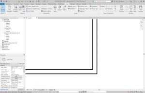
Clicking on the Thin Lines icon lets users control the finer objects in a model. Since there are no layers in Revit, line weights end up being controlled by the objects they represent.
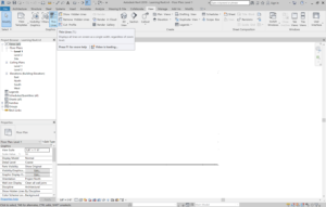
Clicking the Thin Lines icon forces the view to display the thinnest lines possible for all the objects.
Before Clicking the Thin Lines Button
After Clicking the Thin Lines Button
Displays all objects in 3D. Be careful when turning on shadows as the model will be slowed down!
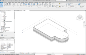
The Visual Style button in the View Control Bar allows users to view their model in color.
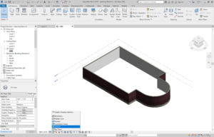
The ViewCube located at the top right corner of the view window allows users to switch between different perspectives of their model.
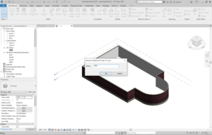
A view can be locked by pressing lock icon at the bottom left corner in the View Control Bar. Afterwards, it will prompt users to name the view.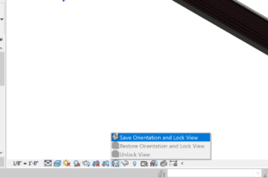
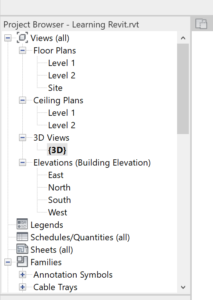
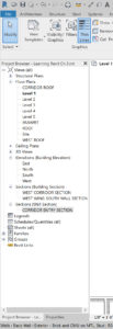
The Project Browser is located on the left of the Revit interface. It is to the left of the view window.
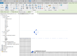
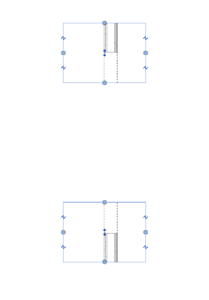
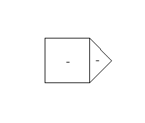
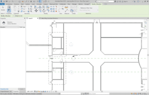
They are elevation markers and are seen in plan views. They can be moved.
There are 2 parts.
- The triangle component is the elevation.
- The square box is the part of the marker that has the sheet number on which the elevation will be in. Make sure to move both together, not separately.
Close a view by clicking on the ‘X‘ by the window’s name.
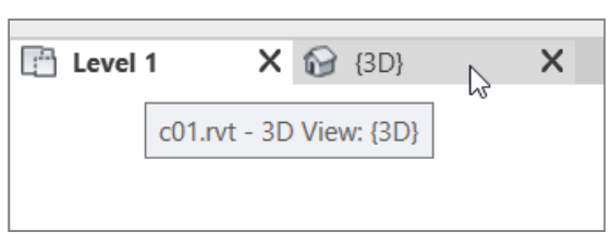
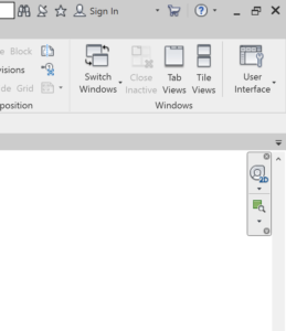
Multiple inactive views can be deleted by hitting the Close Inactive button within the View Tab.
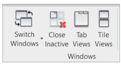
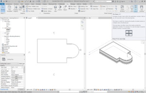
Clicking on the Tile Views icon in the View Tab will display the views side by side.
The number of backups can be changed within the File Save Options menu.
This can be found within the Save As Dialog and clicking on the Options button. You can also change the view for the thumbnail preview.
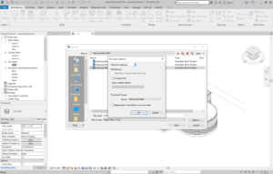
Revit has this feature because every time you click on the Save Option, it duplicates the file. It then adds a number to the end of file name (ex: 0001).
The default amount of backups is 3 times. Once it has gone though the process 3 times it will start replacing the 0001, 0002, 0003, files with the most current files.
There are 2 types –
- System Families
- Hosted Families
A System Family is only found in a Revit model and can’t be stored in a separate location. They are inherent to the model and can be modified through its element properties.
System Families are able to define a model.
They are:
- Walls
- Floors
- Roofs
- Ceilings
- Stairs
- Ramps
- Shafts
- Rooms
- Schedules/Quantity Takeoffs
- Text
- Dimensions
- Views
A Hosted Family is inserted into a block and can be stored in an external directory. The file extension for a hosted family is .rfa.
Hosted Families are hosted in a way by a system family.
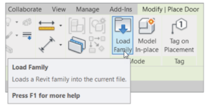
To insert a Hosted Family into a model:
- Go to the view where the hosted family will be inserted.
- Use the Load Family button within the Modify tab to open the Load Family dialog.
- Browse to find the family you would like to insert into your model and choose your specific family.
- Insert the hosted family into the model accordingly.
After a Hosted Family is inserted into a model it becomes part of the model.
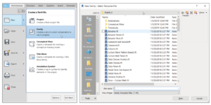
- Click the File Tab, select New and then click on Family. This will open the browse dialog.
- Browse through the templates and choose the one you’d like.
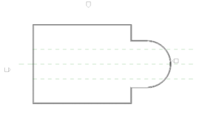
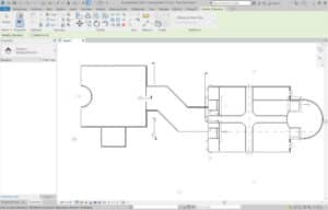
A Reference Plane helps layout a building. They are construction lines that users can place in their Revit model to establish centerlines and use as an aid for symmetrical geometry.
When a Reference Plane is added in one view it will also appear in other views
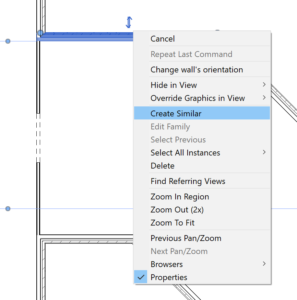
Right-click on an existing wall and click on Create Similar.
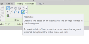
It is within the Draw Panel in the Modify Place Wall Panel.
The Pick Lines command let’s you add a wall by using an offset from another object/wall.
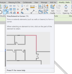
You can activate the Trim command by clicking on the Trim icon or using the (TR) shortcut! The Trim Icon appears in the Modify | Walls Panel after selecting a wall.
Use the Measure Icon and pick to points to Measure.
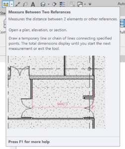
The Temporary Dimensions function allows your to control where Revit measures the temporary dimensions.
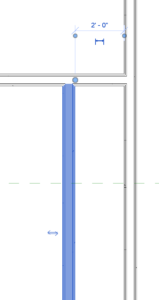
A Temporary Dimension in Revit appears when an object is selected. By clicking on the grips that appear after selecting an object you can control what a Temporary Dimension is measuring.
The actual increment of the temporary dimension appears in blue numbers, you can adjust this number and it will change the dimension by moving the selected object in accordance with the new increment.
When you are looking at a Temporary Dimension click on the icon that appears below it to make it a permanent dimension.
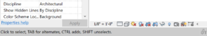
If you accidentally selected too many objects press the Shift Key and click on the items you want to deselect.
This will remove an item from your selection set.
To add objects to your selection press the CTRL key and click on the items you want to add to your selection.
Your cursor will let you know if you are adding or subtracting items.
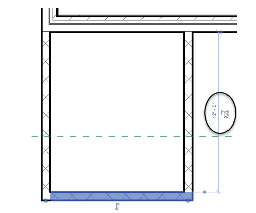
The Wall Joins function allows you to view how walls in a specific area are joined and edit them as well.
The Wall Join Display option is within the Properties panel.
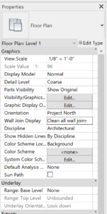
The Wall Join Display option is not selectable unless the model’s detail is set to Coarse.
Clean All Wall Joins
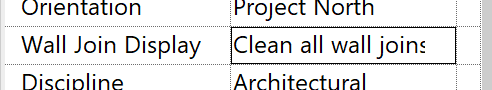
This joins the same material in each wall, regardless of the wall type.
Clean Same Type Wall Joins
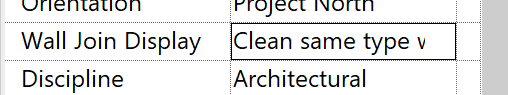
This joins clean joins only within walls of same type
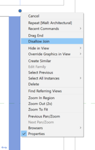
Right-click on the blue grip that is next to the end of wall and click on Disallow Join.
You can now drag the same blue grip to determine where you want to end the wall.
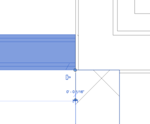
After you disallow a wall join, you can join it back up by clicking on the blue T-shaped icon.
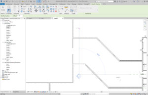
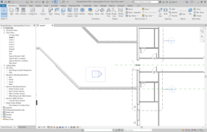
A plan view in Revit is taken automatically at 4′-0” (1200 mm) up the wall from the finish floor. You can manually edit the profile of a wall cut in plan.
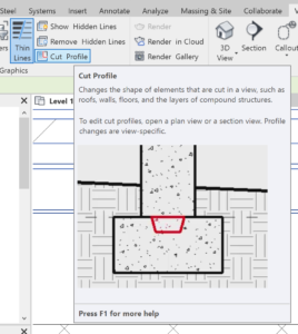
To accomplish this:
- Go to the Graphics panel in the View Tab, and Select the Cut Profile Button
- Click the face of the material you’d like to be cut
- Draw a short line of where to cut the material, an arrow will then appear that points to the side of the material that will be kept. To switch the direction of the arrow click on it to flip the direction.
- The view that appears while you are performing these steps is called Sketch Mode. When you have finished click Finish Edit Mode and you will now see the final result.
- Make sure you are on Floor Plan Level 1
- In the Architecture Tab, click the Door Button
- Then click on the Load Family Button
- Go to Doors directory and select the type of door you’d like and click Open
When placing a door you can press the Spacebar to change its orientation and move the cursor up or down to flip the direction of the Door.
Revit will not allow you to place a door into blank space as a door is considered a hosted family and needs a wall into which it must be embedded.
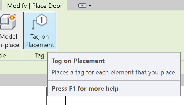
You can also select to place a door tag when adding a door.
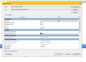
- Select the wall where door is placed
- Within the properties panel, click on the Edit Type button
- A pop-up menu will appear.
- In the Wrapping at Inserts drop down menu within the Construction category select Both
- Click OK and your model will be updated.
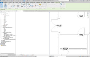
- Select the door or door tag
- Click on the number in the door tag
- Adjust the number to what you’d like
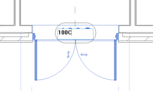
Door tags display an instance property and are assigned in sequential order
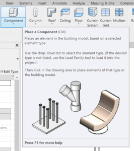
- Go to the Architecture tab and click on the Component button
- On the Modify | Place Component Tab, click on the Load Family Button
- Browse the Openings Directory and select your desired opening
- Click OK
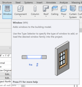
- Go to the Architecture tab and click the Window button
- In the Type Selector, select the type of Window that will be added. At this time you can also select the Tag on Placement button if you’d like the Window to display a Tag.
- Add the Window to your model
- Select a window and go to the properties panel
- Click the Edit Type Button
- The Type Properties Menu will appear allowing you to make any changes
Window tags display the Type Mark property and will be assigned based on the type of window
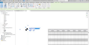
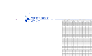
1. Go to the Architecture Tab and click on the Level Button.
2. In the Modify | Place Label Tab go to the Draw Panel where you can either choose to add a new level by picking a line or drawing a line. If you have other levels already set go to Pick Lines.
3. Within the Options Bar, select Make Plan View if you’d like a new floor plan to be created as well.
4. At the end of the Options Bar within the Offset Field enter the distance to offset the new level.
5. Hover your cursor over the level to offset and you will see a blue dotted line appear either over or under the existing level. Make sure to hover slightly above the existing level.
6. Click to make your selection and continue to add more levels if needed.
7. Press ESC to exit the command when finished
If a selected level has a bubble that turns blue when selected that means it has a plan associated with it, if it remains black there is not plan associated with it.
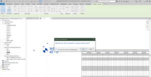
1. Zoom in on the level and click the text field of the level which will enable it to be edited
2. Type the new name of the level and press Enter.
3. A pop up menu will appear asking if you’d like the rename any corresponding views with that level. Select Yes.
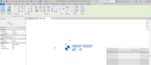
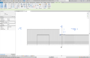
- Zoom on the level and click on the distance field.
- Type in the new distance for the level and press Enter.
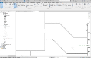
1. Select the level to adjust.
2. Click on Add Elbow – this will bend the level.
 3. You can now edit the level added by moving the blue grip at each bend point.
4. Adjust the position of the level through the grip points.
5. Hit ESC to deselect the level when you’re done.
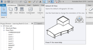
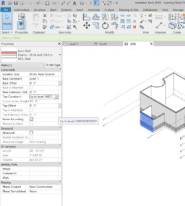
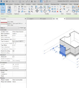
1. Click on the Default 3D View icon within the Quick Access Toolbar.
2. Select the wall that should be extended up to the level.
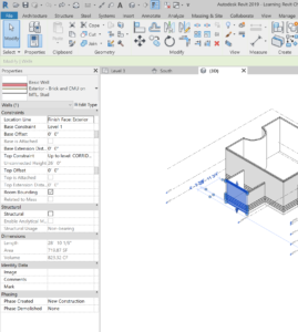
3. Within the Properties Dialog, under the Constraints category change the Top Constraint to Up to Level: (Name of Level) and click Apply.
1. Zoom in to the level to adjust.
2. Click the lock icon to unlock it.

3. Drag the level to where it should be placed.

4. You can also repeat this to the other side of the level.
5. Press ESC when finished.
1. Zoom into the side of level to hide and uncheck the Show Bubble check box to hide the bubble.
2. Display the bubble on the other side of the level by checking the Show Bubble check box.
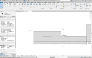
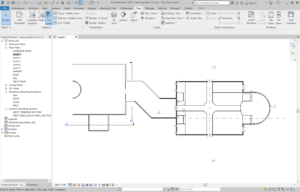
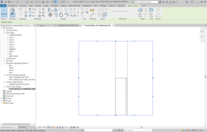
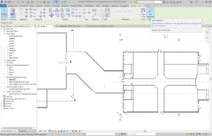
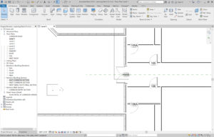
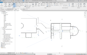
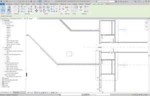
1. Go to Level 1 Floor Plan and zoom in the area to add the section.
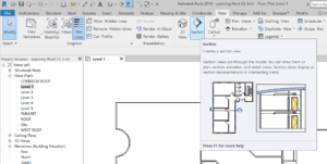
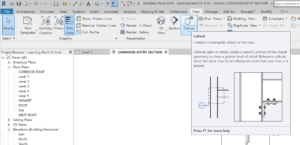
2. Go to the View Tab, and within the Create Panel, choose the Section Button.
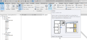
3. A section will need two points to be placed. First, select where to place the head of the section and then pick where the tail will be placed.
4. Click to place the first point and then click to choose the second point of the section.
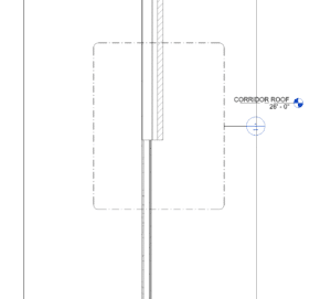
5. When the section is placed a dashed line will form a box around a part of a model depicting the extents of the section. Any part of the model that is not in the box will not be shown.
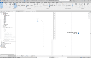
Be sure to give a name to your Section to stay organized and not waste time later on trying to find the right section!
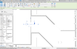
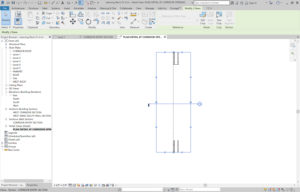
The Gaps in Segments Icon is the small blue break icon in the middle of the section.
Clicking on this icon will add a gap to the section and allow you to move the grips of the section.
With the Section selected, click on the symbol that is similar to the recycle icon, which will allow you to display a section head, tail, or nothing at all.
1. Go to Level 1 within the Project Browser Panel.
2. Within the View Tab click the Section Button.
3. In the Properties Panel select Wall Section.
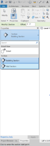
4. Add the Section within your model.
5. Rename your wall section within the Project Browser.
- Open an existing Wall Section.
- Within the View Tab, click on the Section Button.
- Within the Properties Panel, select the type of section to be Detail View: Detail.

4. Place the section within your model.
5. Within the Project Browser Panel there is a new type of category of views named Detail Views (Detail). Rename the Detail View we have just added accordingly.
1. Select the window surrounding the detail.
2. Select the blue grips at each side and stretch them accordingly.
1. While the crop region is selected click on the Break Icon.
2. This breaks up the selected crop region into 2.
1. You can move a Crop Region by clicking on the arrows and dragging the region to place it where desired.

1. Click on the Level 1 Floor Plan
2. Within the View Tab, click on the Section Button.
3. In the type selector, click on Building Section
4. Place your building Section within the model
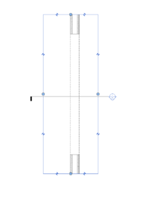
5. Select your Section and within the Modify | Views Tab, click on the Split Segment button.
6. Choose where in the Section you’d like to split it.
1. Go to the View Tab within the Ribbon.
2. Click on the Callout button.
3. Create the Window of where you’d like your Callout to go.
4. The new Callout View will be placed within the Sections Category – you can rename it accordingly.
A Callout typically has blue grips that can be dragged to change the size of the callout.
You can also adjust the placement of the leader within the callout to create an elbow.
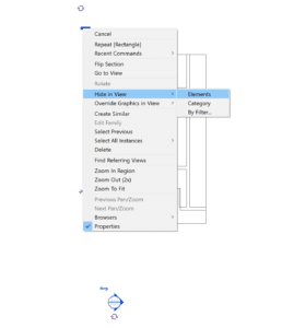
1. Right-click on the element to hide.
2. Select Hide in View and click on Elements.
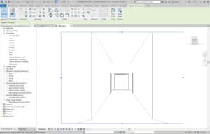
1. Go to the View tab, click on the drop down menu of the 3D View button and click on Camera.
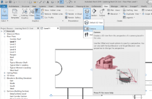
2. Add the camera in the model with the view you would like to create. The first point is where the camera will go and the second point designates how far the camera reaches.
3. You have now created a camera view. After your place your view Revit automatically opens it.
1. Click on the Detail Level and change it to Fine.
- Go to the view Level 1 and in the Project Browser Panel right-click the name of the perspective view and click on Show Camera.
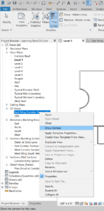
The camera will appear momentarily allowing you to edit it placement within the model.
1. After selecting the view of your camera, in the Properties Panel you can change the view settings of the camera.
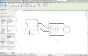
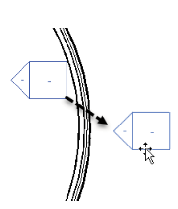
Elevation Markers are represented by the icon that resembles a house. The square box of the icon represents the elevation while the triangle is the part of the marker that activates the view.
1. Move an elevation marker by first creating a window around the entire elevation marker. It is essential to select both the elevation and the view.
2. The cursor will then turn into a Move icon, allowing you to move the elevation marker where necessary. You can now move the elevation marker to your desired location.

1. Go to the View Tab and click on the Elevation Button.
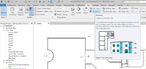
2. Make sure that within the Properties Panel that Building Elevation is selected.
3. As you move your cursor around the building you will see elevation icon change and adjust itself to the building.
4. Click on the model space to place the Elevation Marker within the model. Once your are done press the ESC key to exit the command.
Adding an Interior Elevation follows the same process as adding an Exterior Elevation –
- Go to Level 1 Floor Plan.
- Within the View Tab click on the Elevation Button.
- In the Properties Panel in the type selector, click on Interior Elevation.
- Place the new elevation within your model. Press the ESC key to end the command. If the extents of the interior elevation fall outside the model drag them to be within the interior extents.
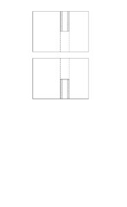
1. Click on the center of the Interior Elevation icon.
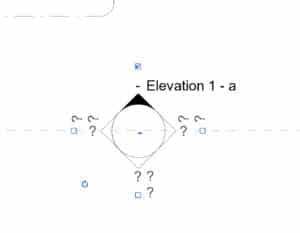
2. Use the checkboxes to decide which elevations should be turned on.
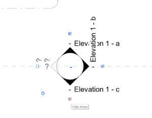
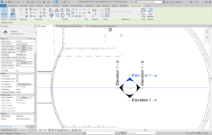
1. Select the Elevation you would like to view the properties and within the Properties Panel you will see a variety of options.
2. Under the Identity Data section you will be able to change the name of the elevation.
1. Go to the Manage Tab, select Additional Settings, and click on Elevation Tags.
2. Within the pop up panel you can go ahead and change the properties of the elevation tag.
3. Click OK when you are done making your changes