How to Model an Axon in Rhino
Software Used:
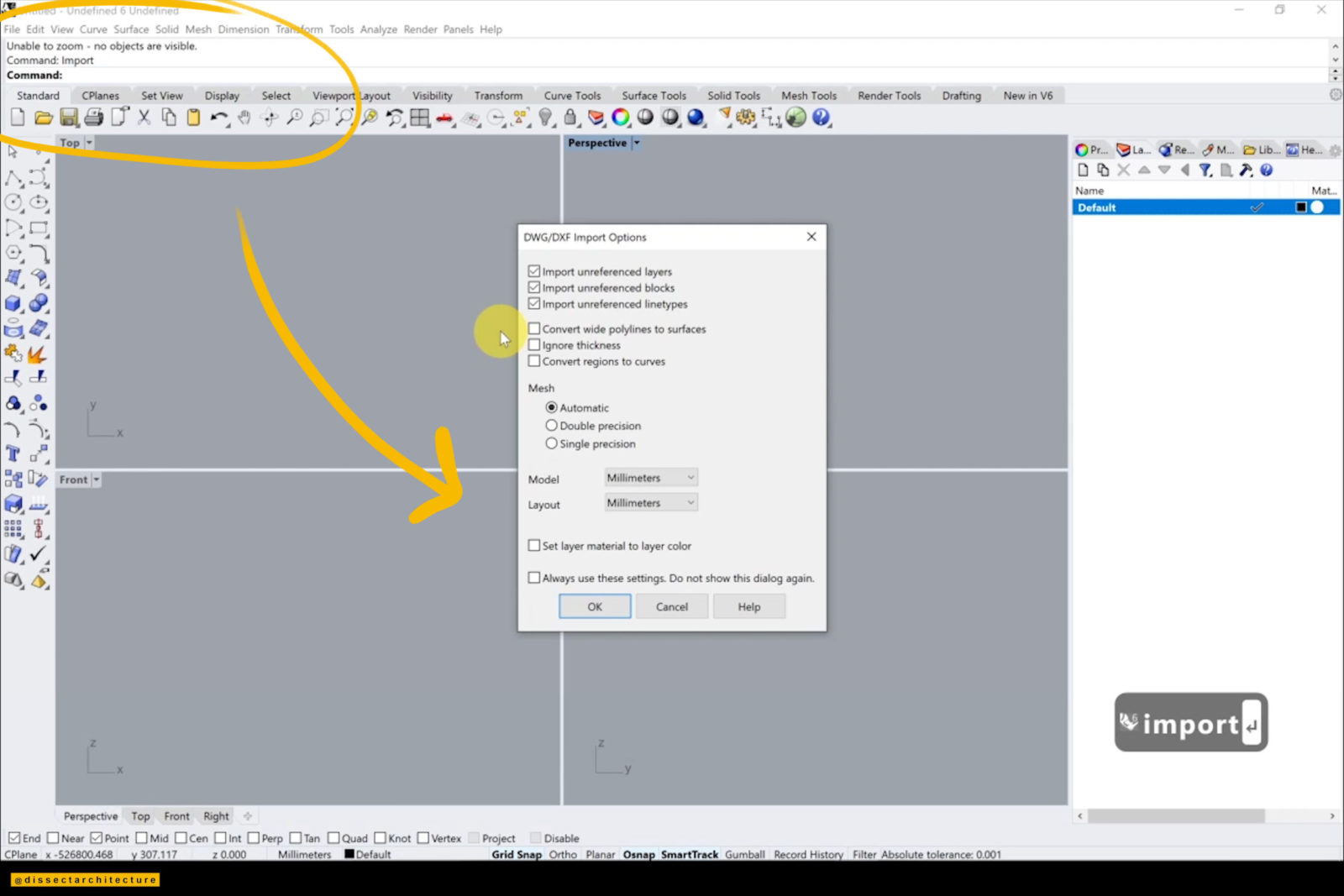
Step 01
Start by opening Rhinoceros 3D and import the CAD file that will be used to model an axon in Rhino with the Import command.
A pop-up panel will appear that will allows you to adjust your units if needed. I will be using inches. After you click OK, your drawing will now be visible in all viewports.
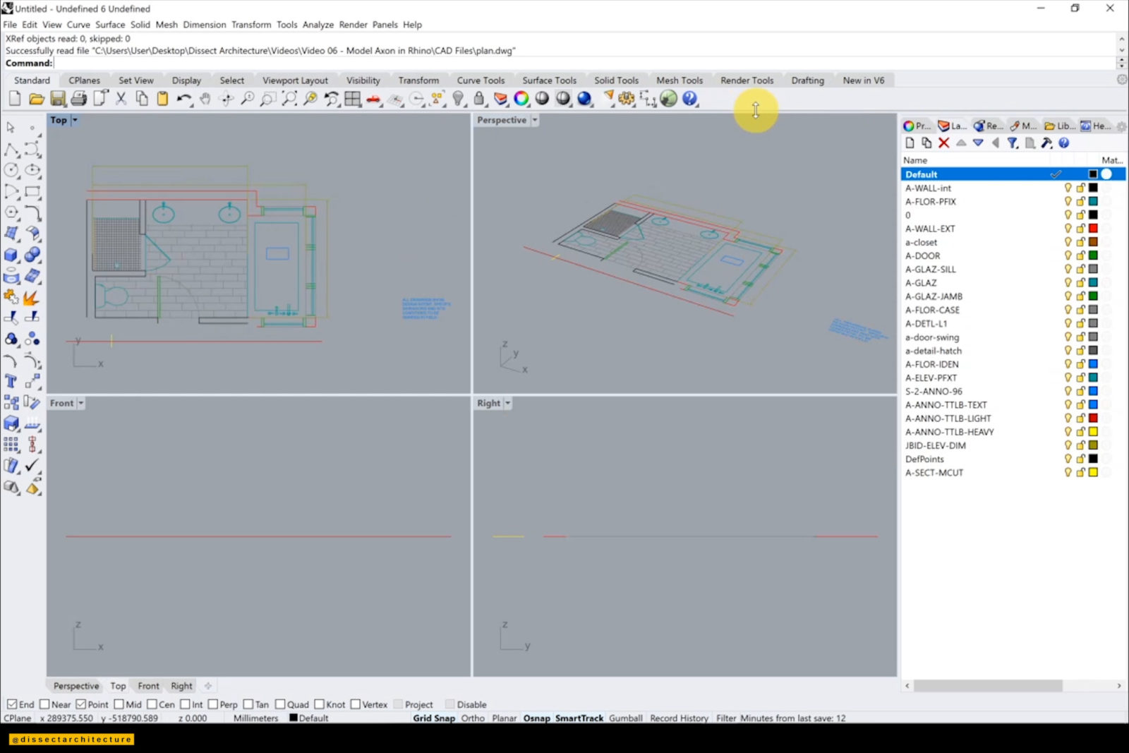
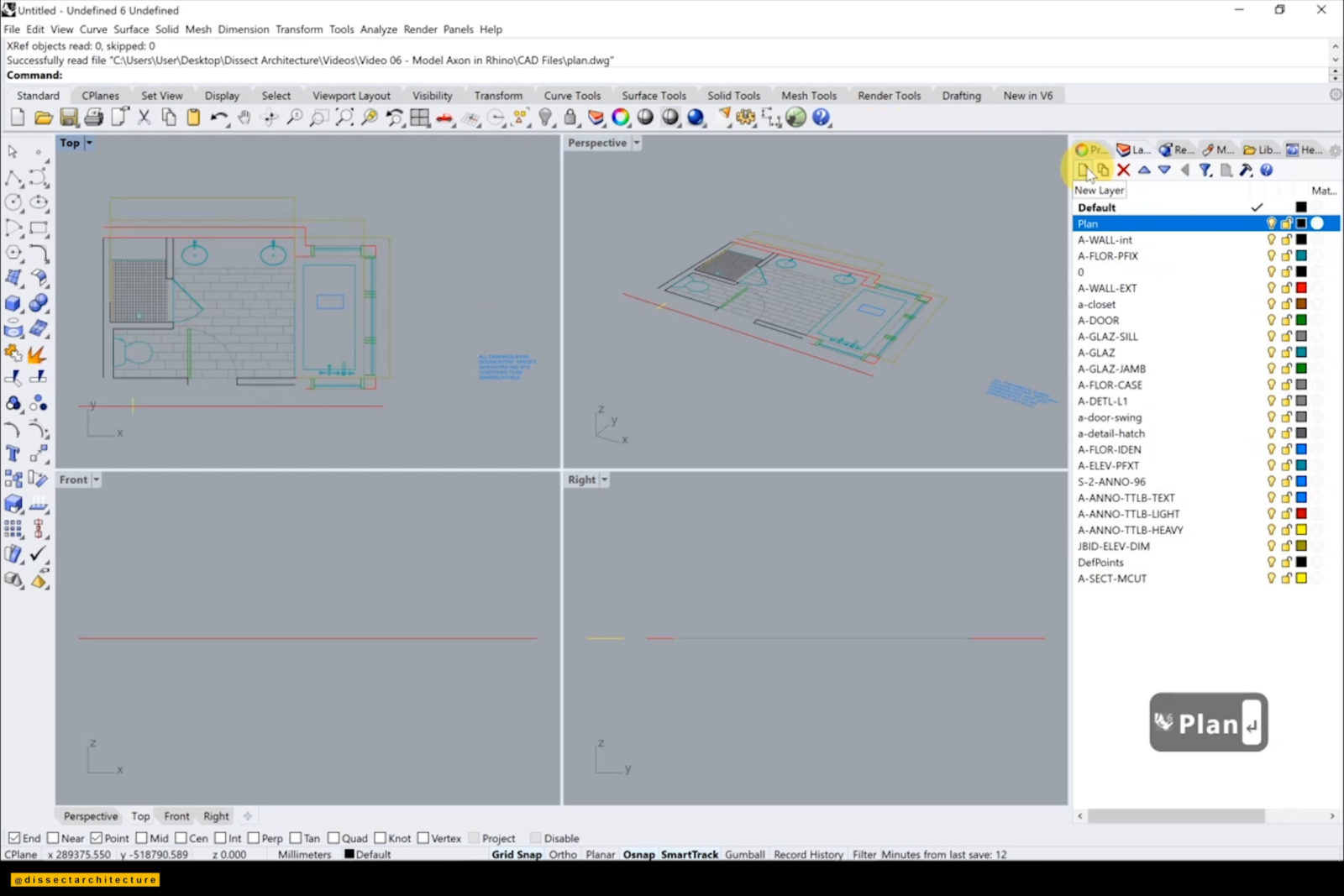
Step 02
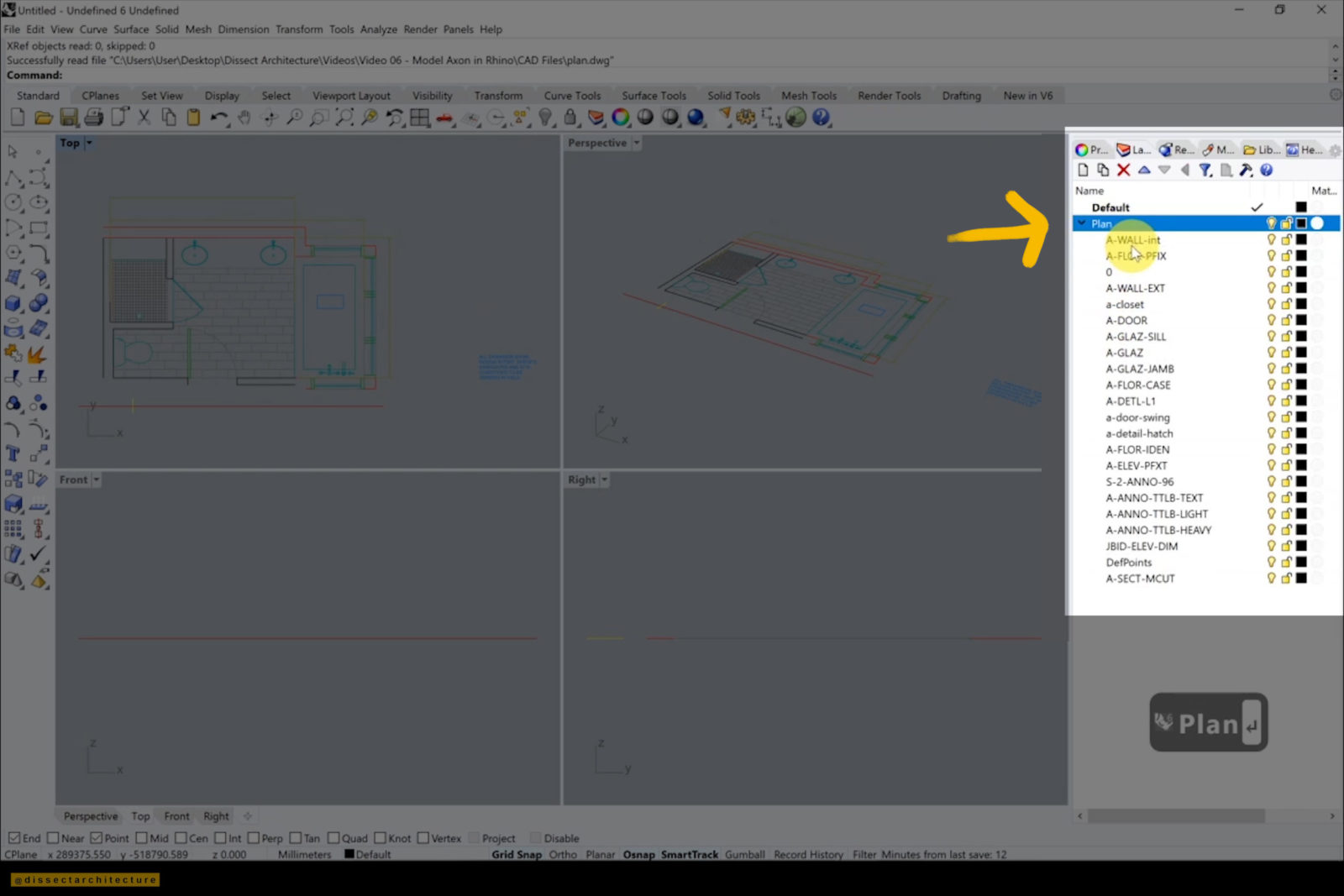
If you look in the Layers Panel you will see that all the layers from your CAD file were imported as they were. To organize the layers, I am going to subgroup them into 1 layer and change the visible color to black.
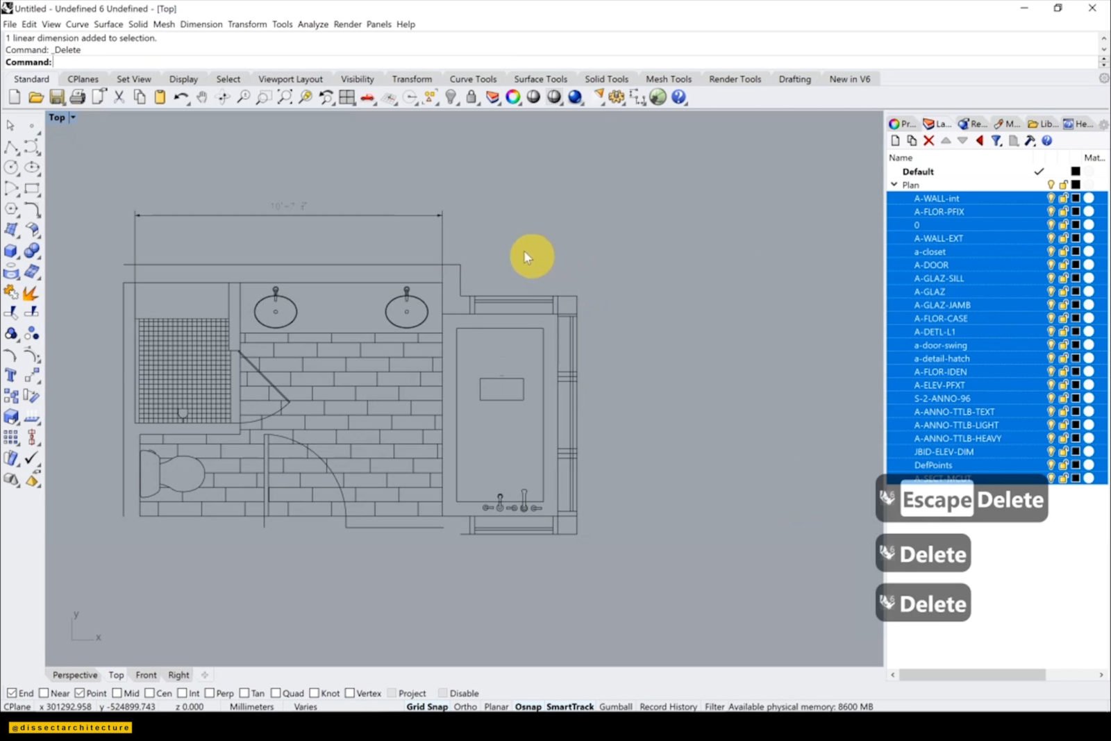
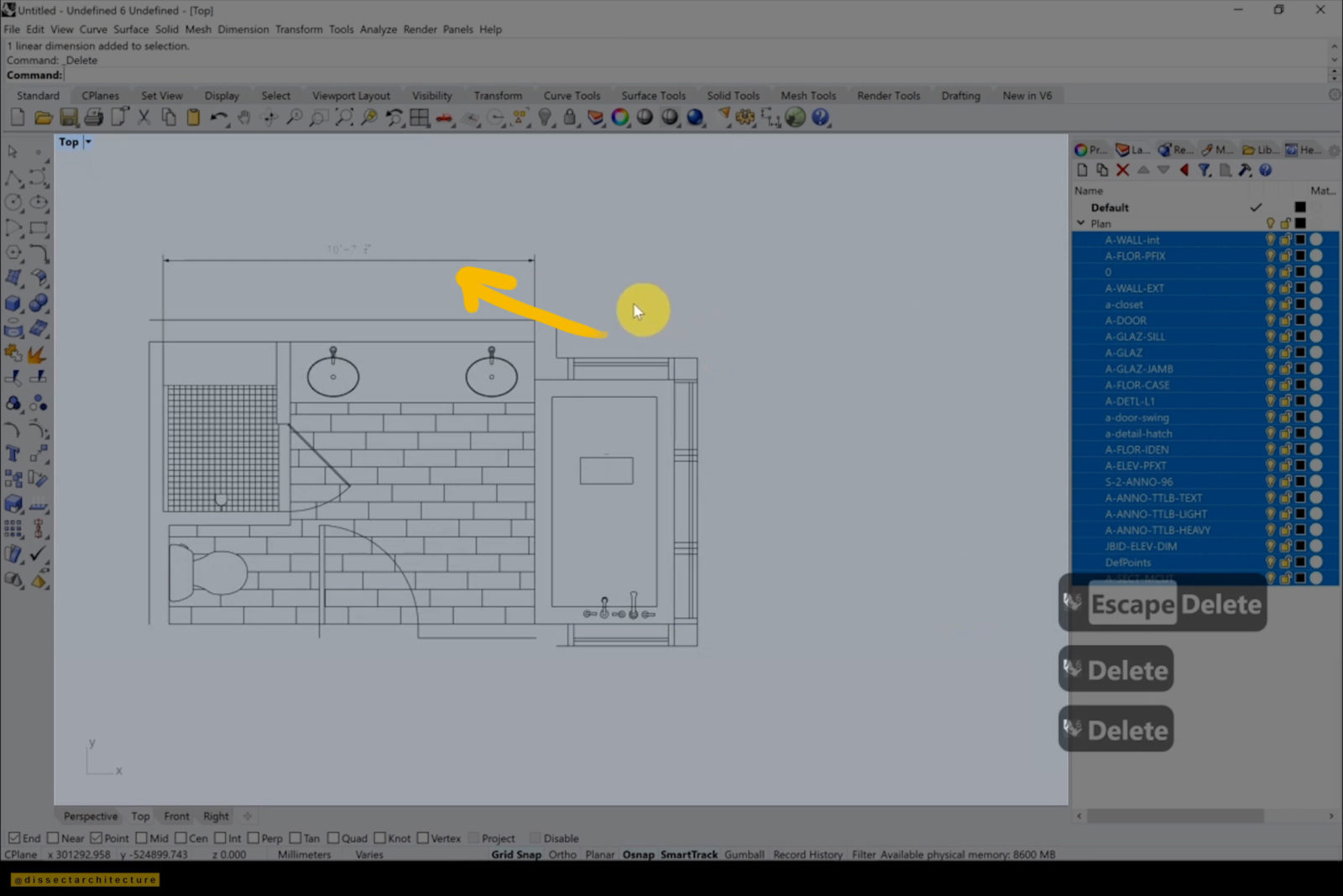
Step 03
Then, go through the drawing and delete all the unnecessary linework like the dimensions. Afterwards, delete all the layers that no longer contain any linework.
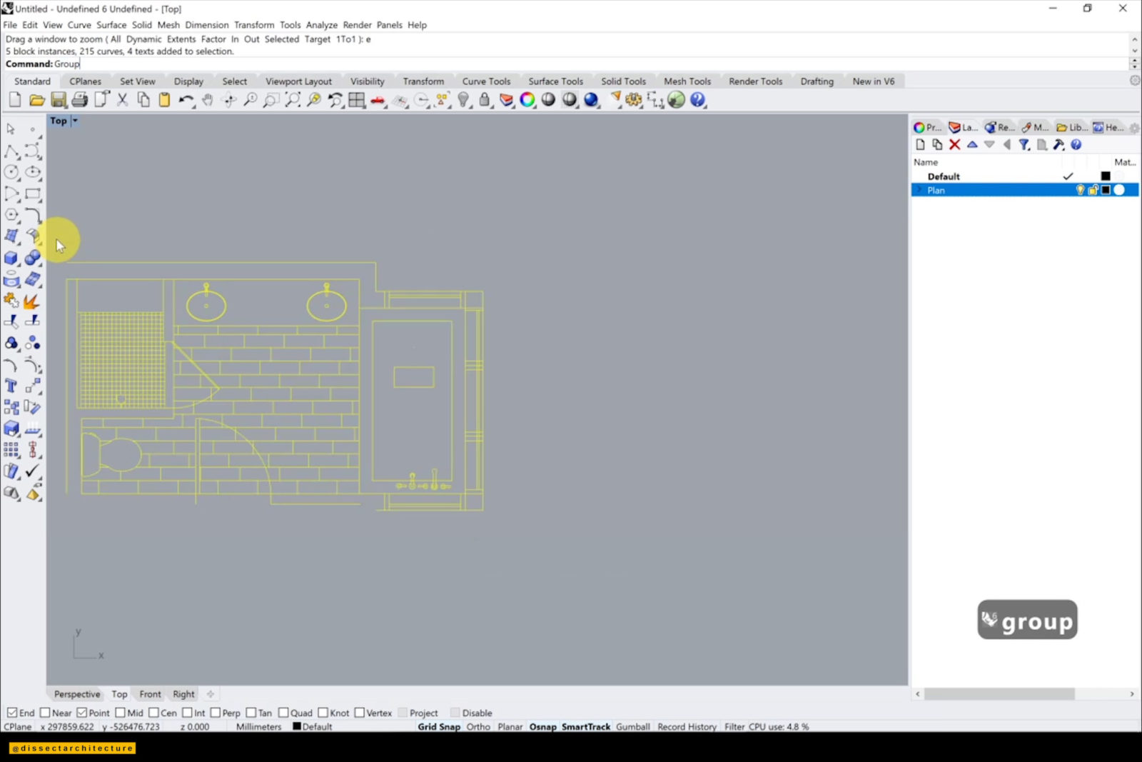
Step 04
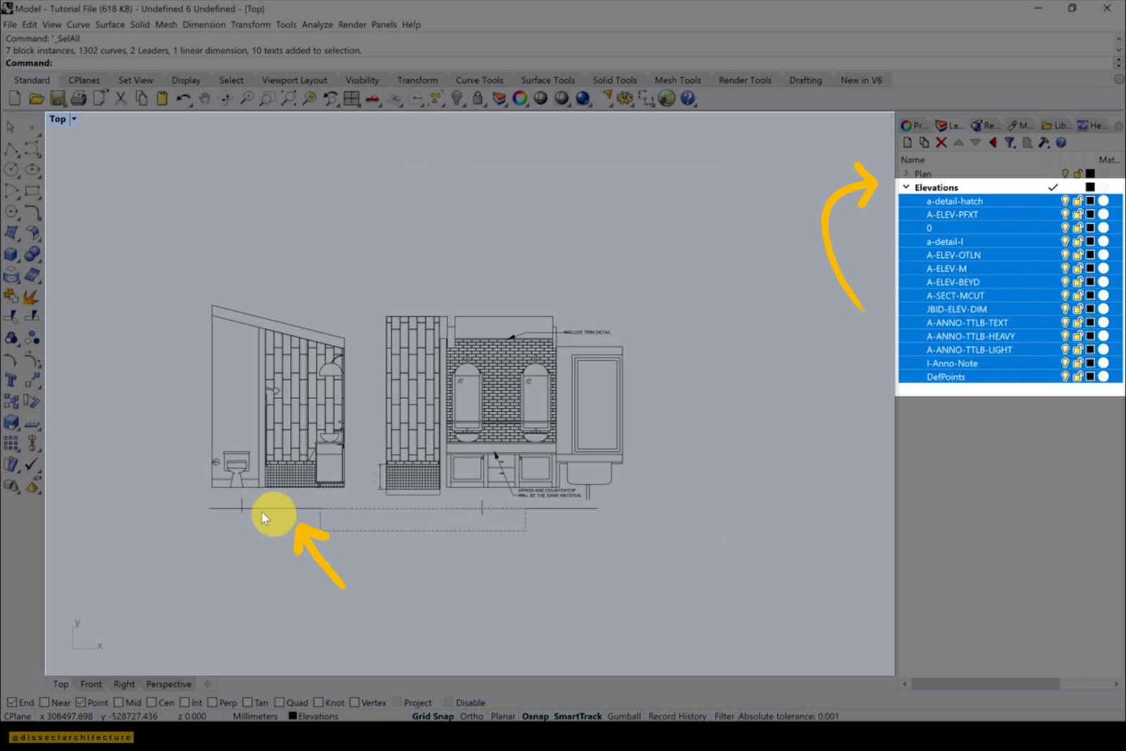
After you are finished, group the plan together by using the Group command. Once the plan is a group, import the elevation of the room to model the axon and delete any unnecessary linework.
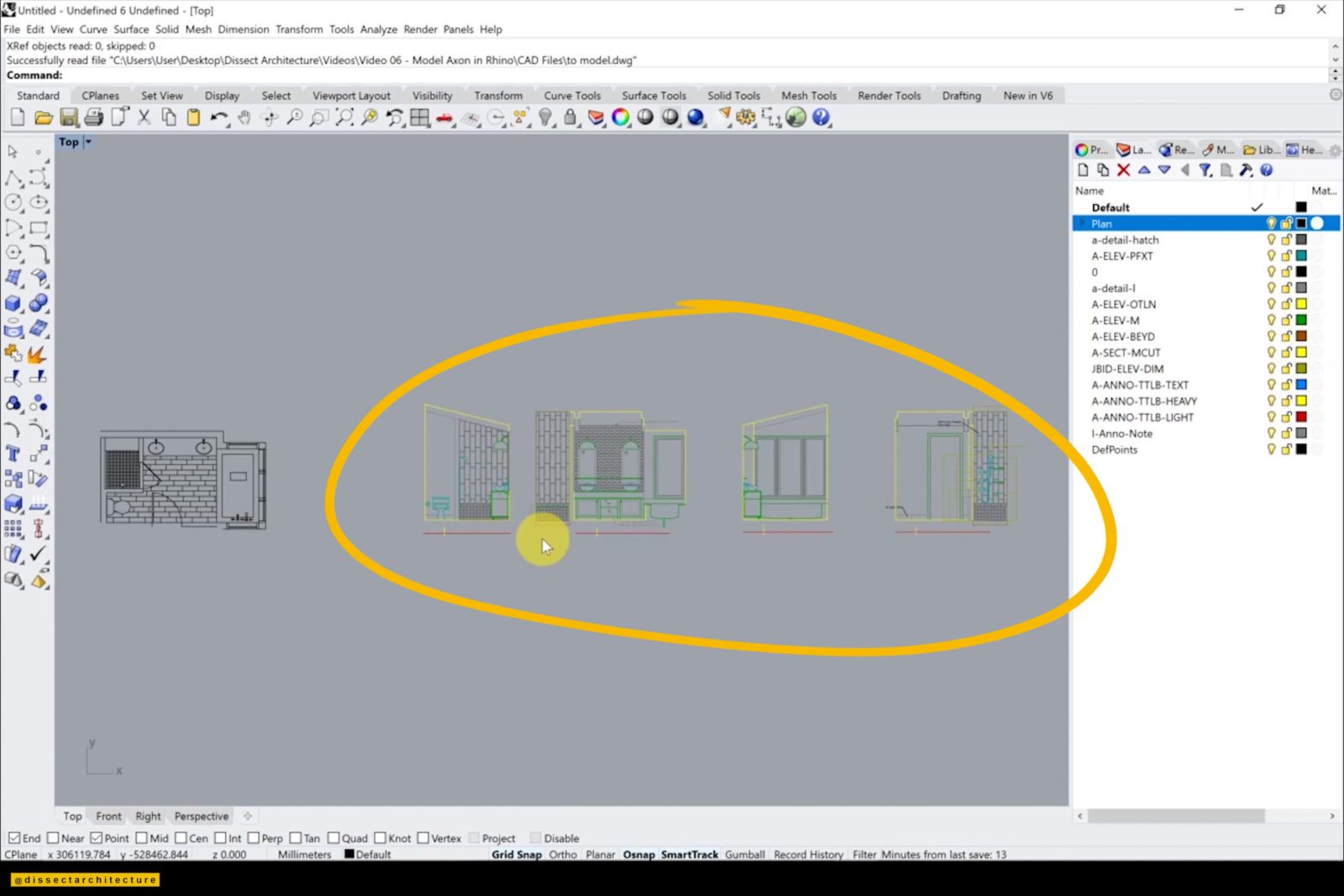
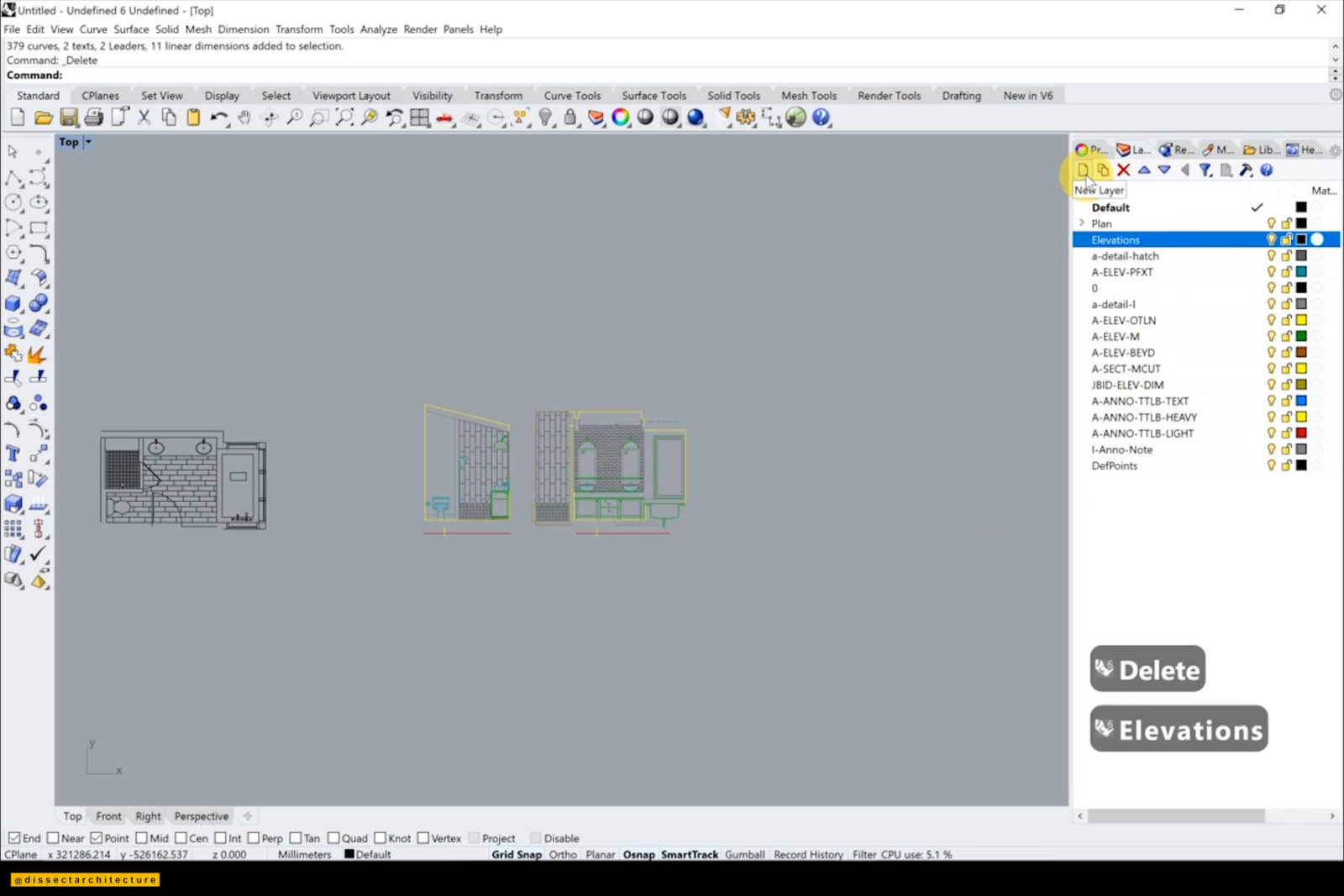
Step 05
Repeat the same technique as before and place all the imported layers from the elevation into their own layer. Again change all the linework color to black and deleted any unnecessary linework.
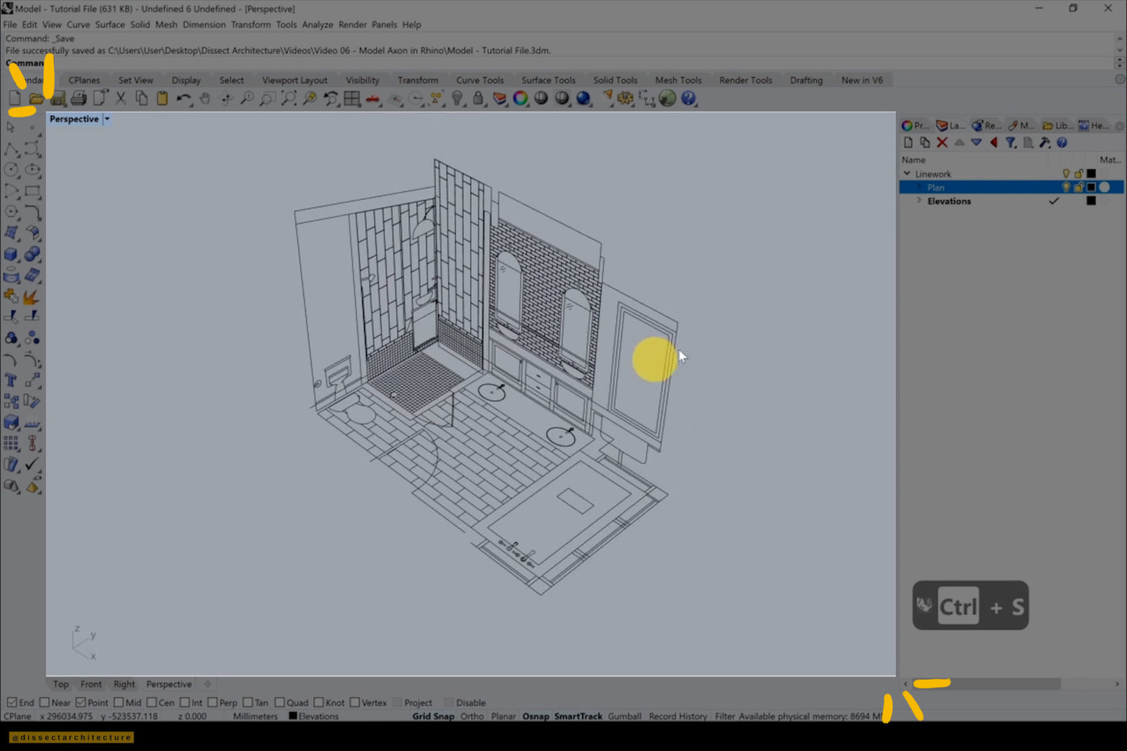
Make sure to save your Rhino file as you are working!
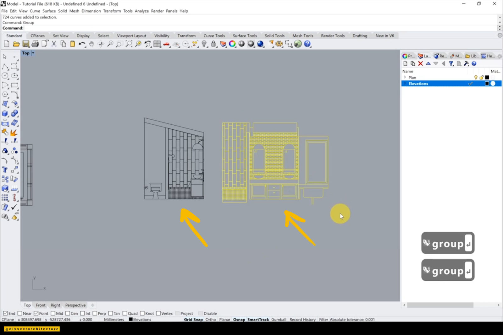
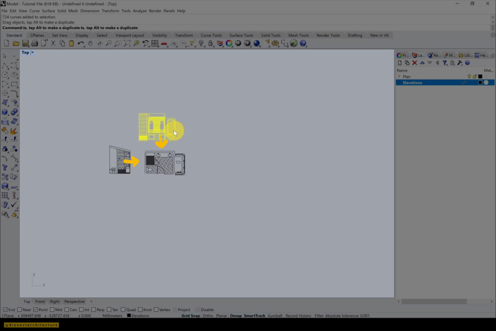
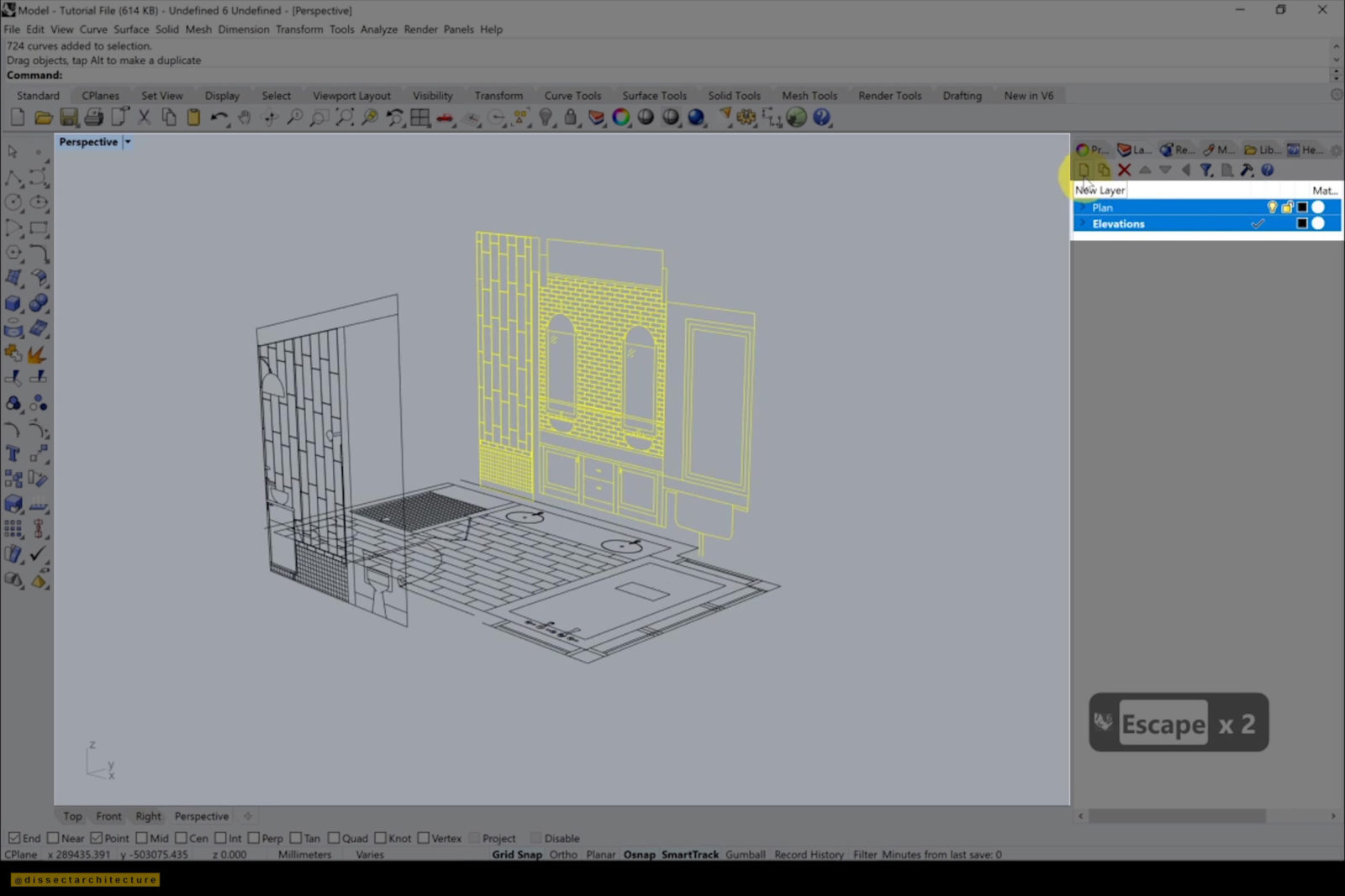
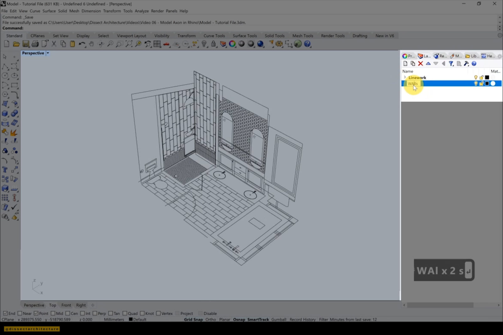
Step 06
Group each layer individually using the Group command and then move each elevation within the Top viewport in accordance with the plan.
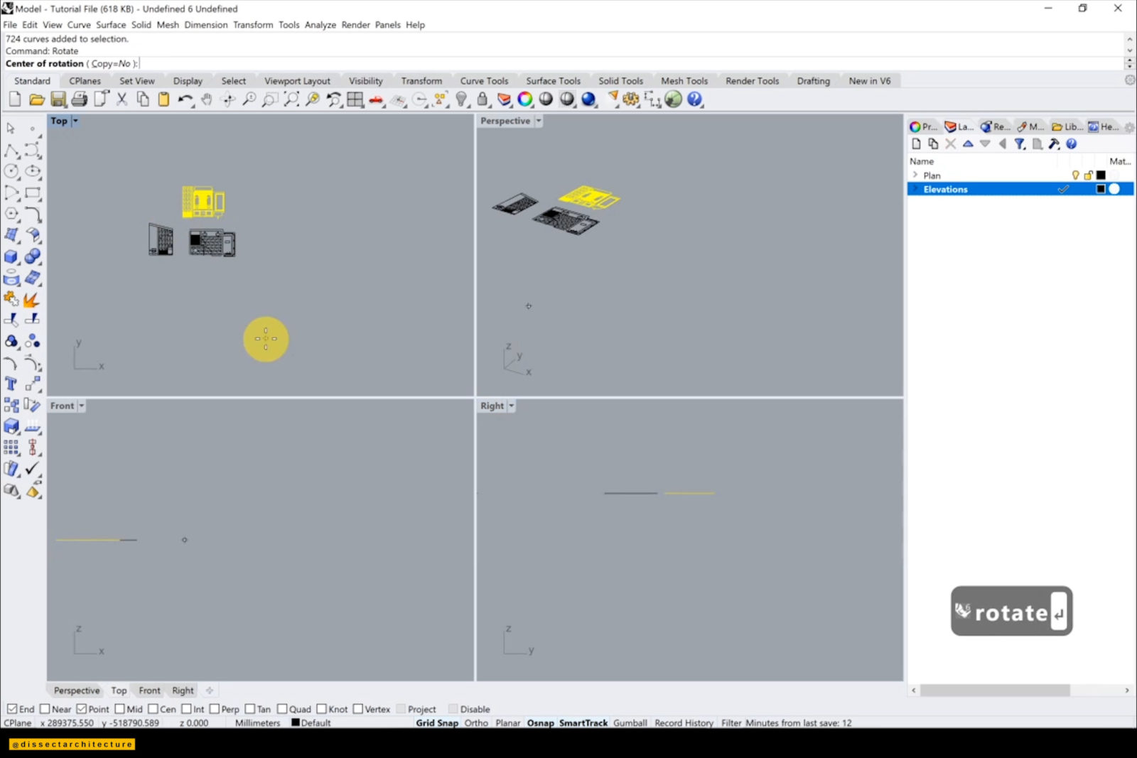
Step 07
Using the Rotate command, rotate each elevation to stand vertically.
Next, create another layer group to place all the linework on. It is important to stay organized with all your layers.
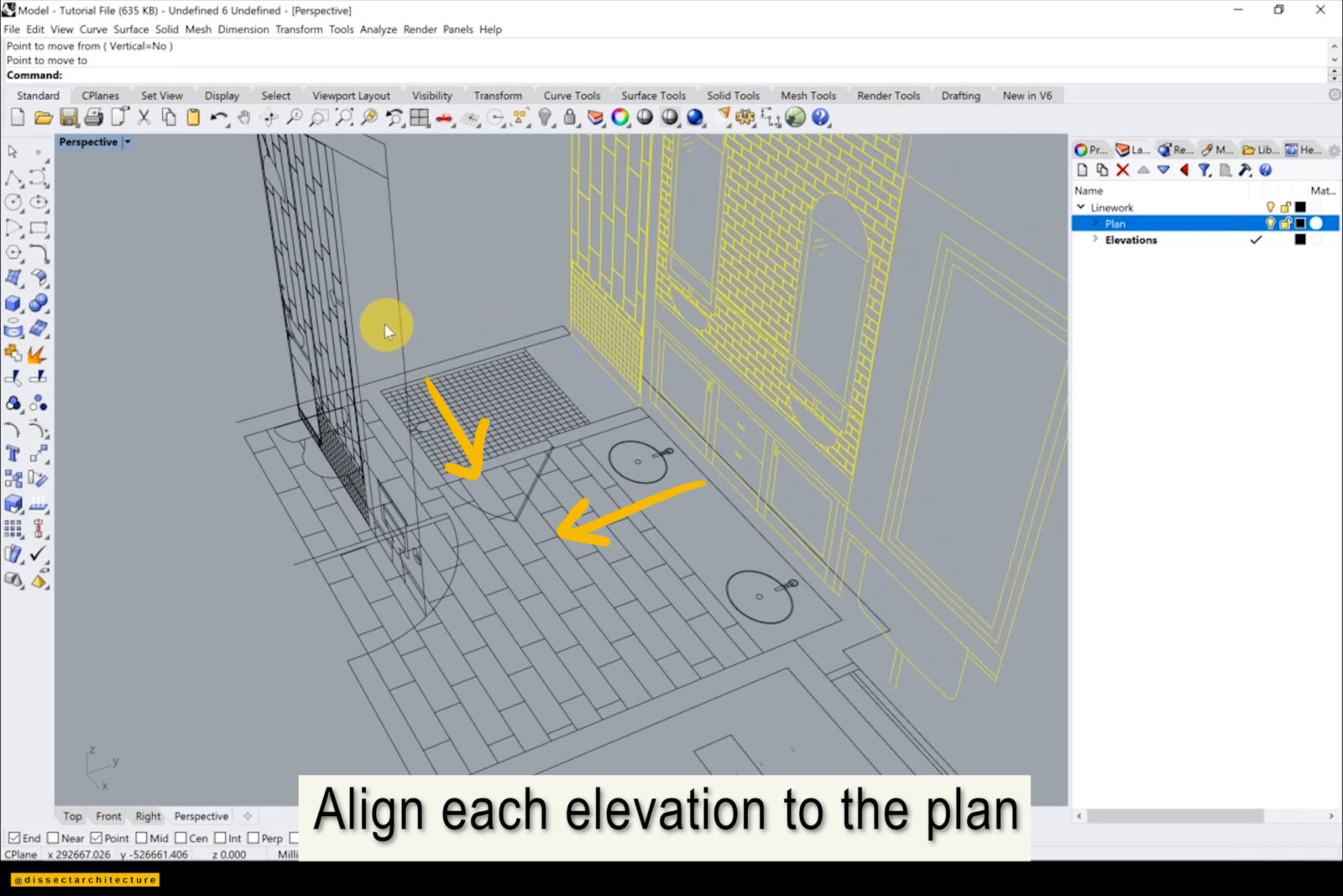
Step 08
Align each elevation to the plan by using the Move command. This is how the linework looks lined up.
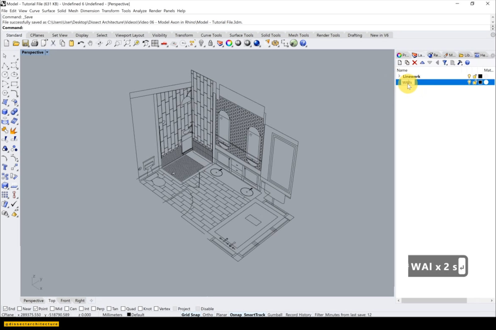
Step 09
Afterwards, make a new layer to start to 3D model an Axon in Rhino.
Begin by modeling the walls. Use the Box command to start modeling the walls using the linework from both the plan and elevations guides.
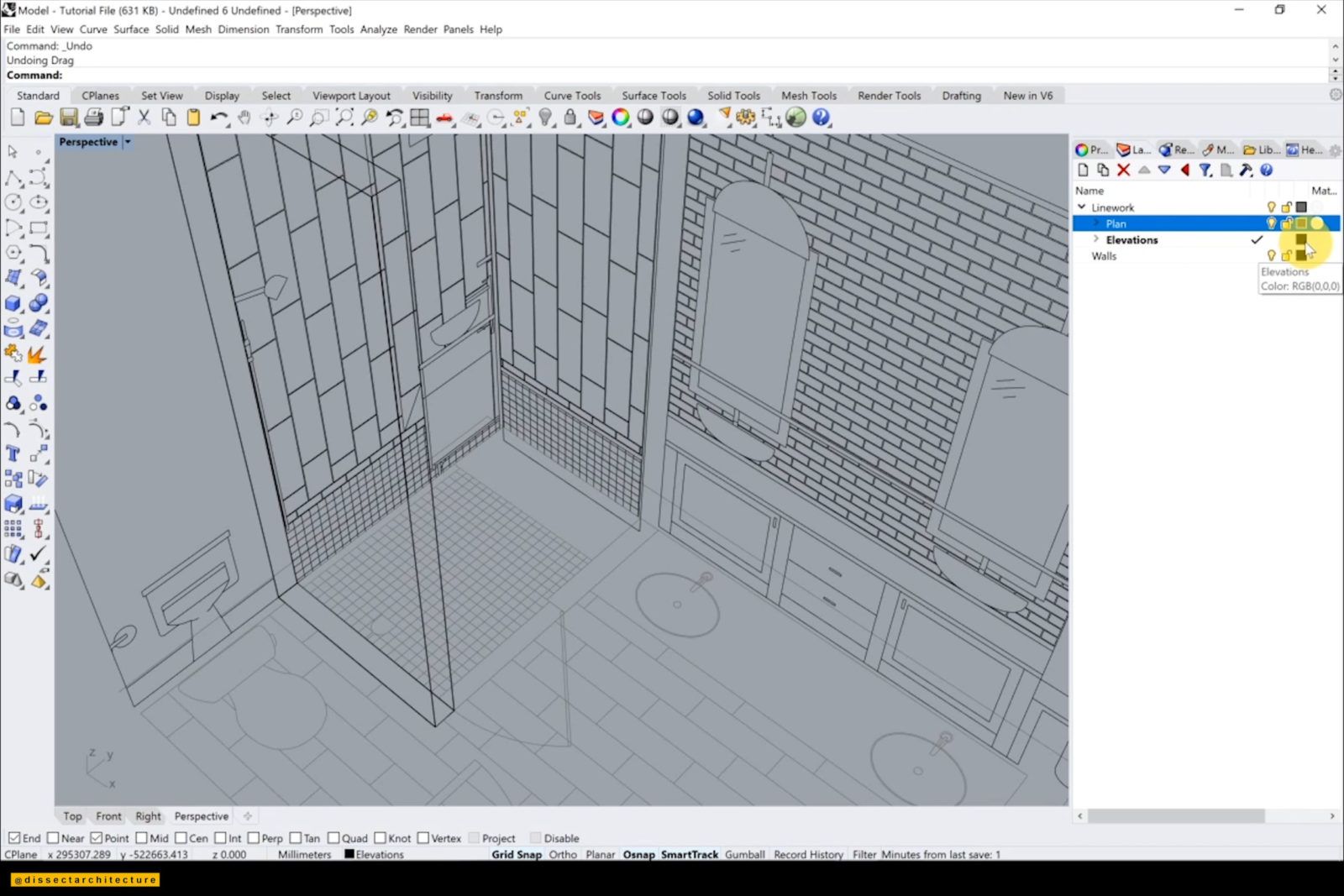
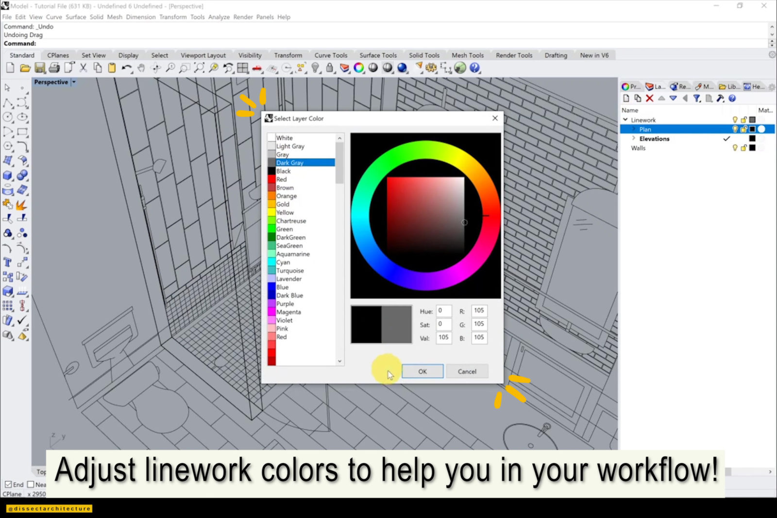
Step 10
If needed adjust the colors of your workspace to help you differentiate between each object.
The Lock command is useful to lock the linework into place so it doesn’t shift while modeling. Use the Scale1D command to make any minor adjustments. I also created the floor with the same technique as the walls.
Step 11
Utilize the linework from the elevation to start modeling the tile on the wall by using the ExtrudeCrv command. I am making the tiles thicker than in reality so it stands out more in the final render.
Then use the Copy command to distribute the tiles along the wall following the tile layout from the elevation. You can follow the linework, or adjust it as you’d like while modeling.
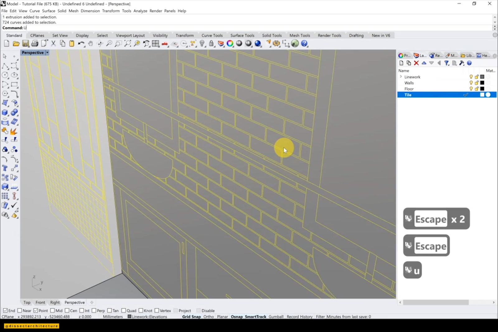
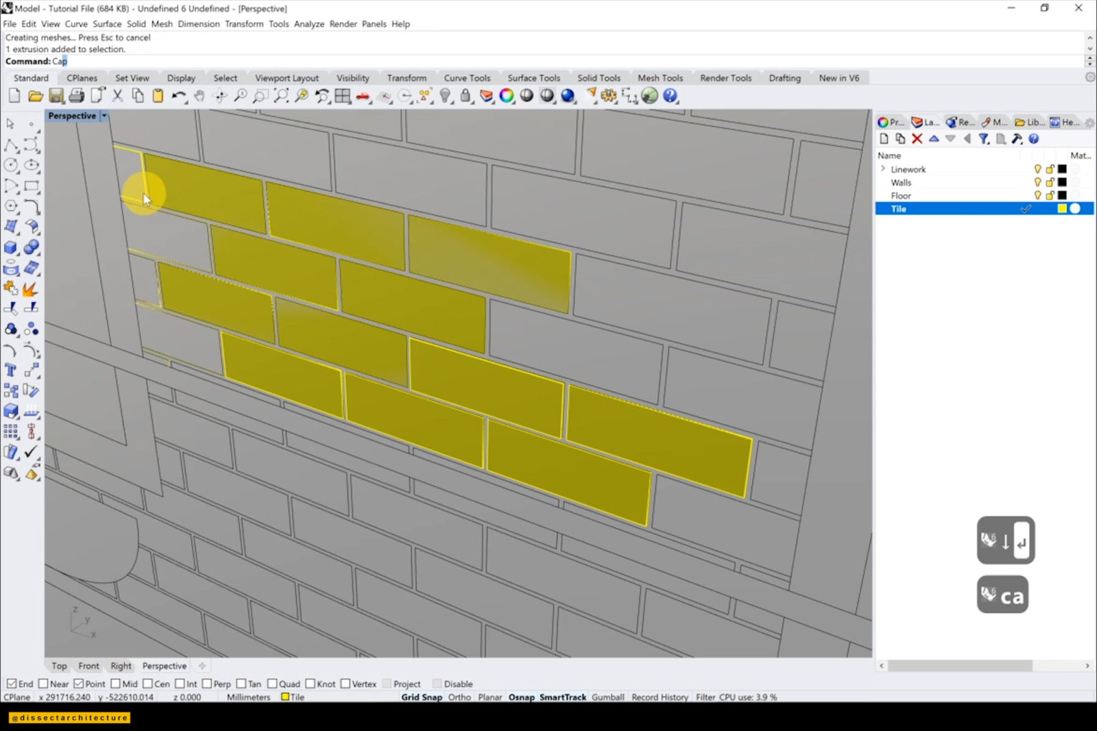
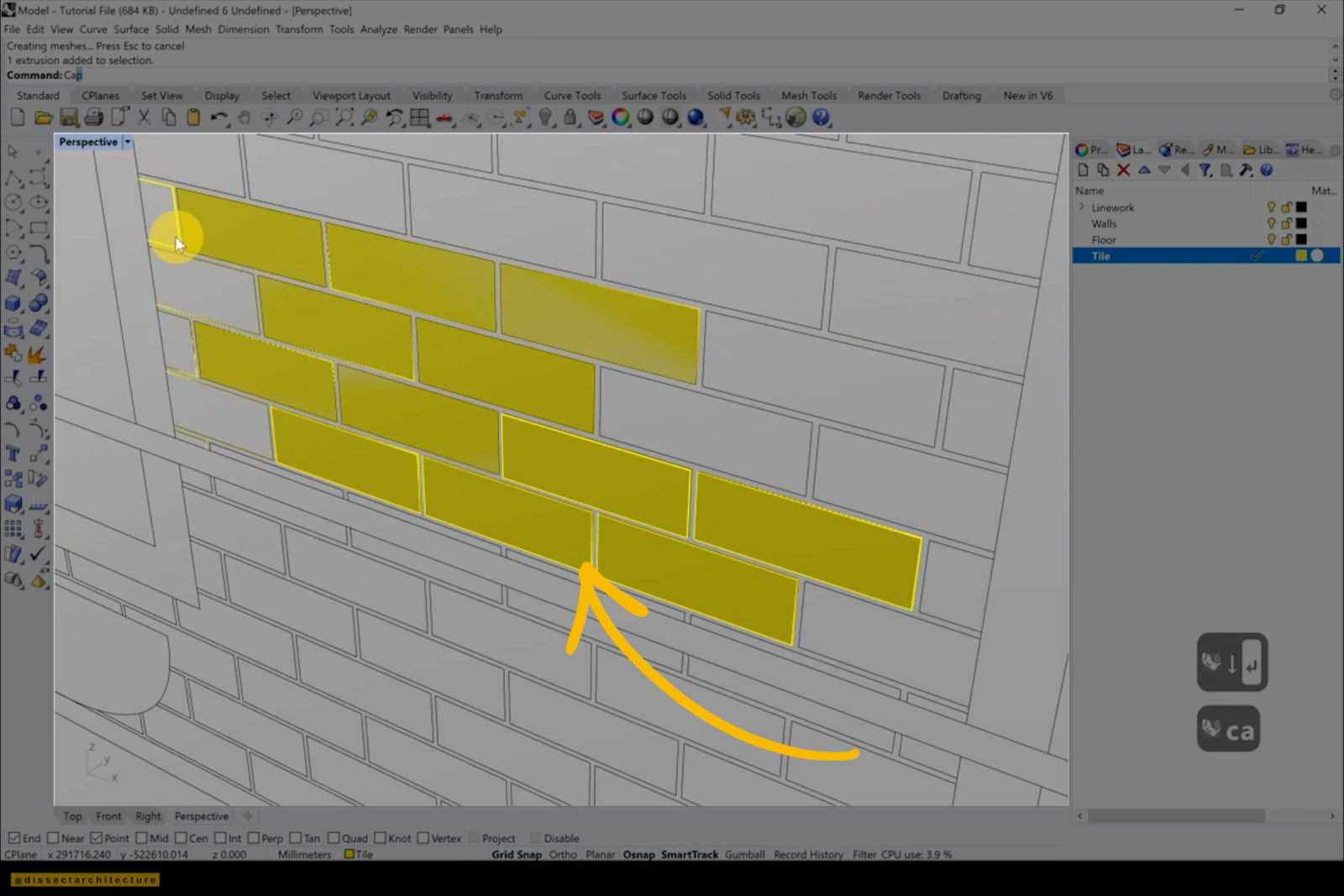
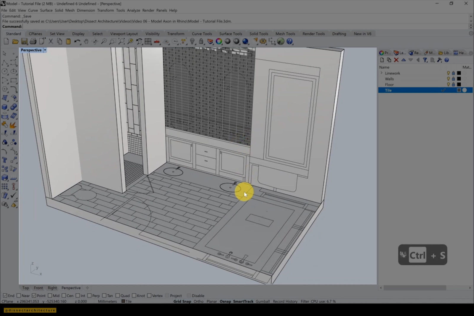
Step 12
I’ve decided to change the color of the tile to yellow so it stands out more while modeling.
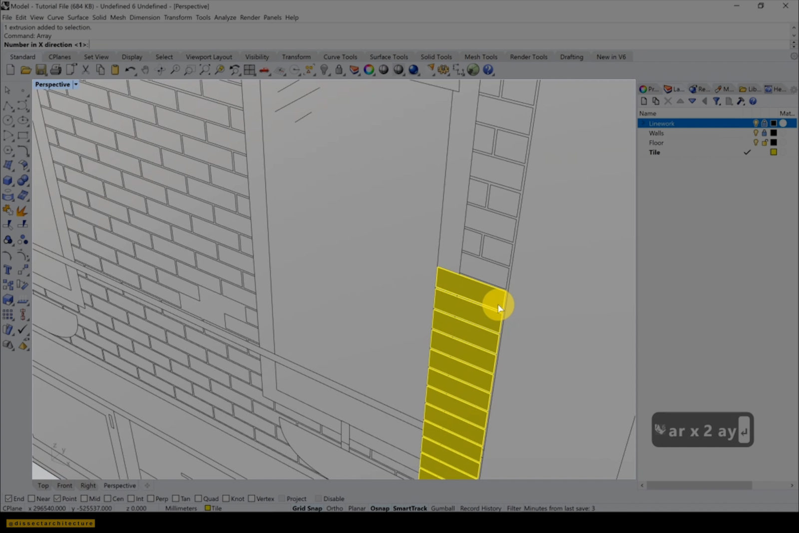
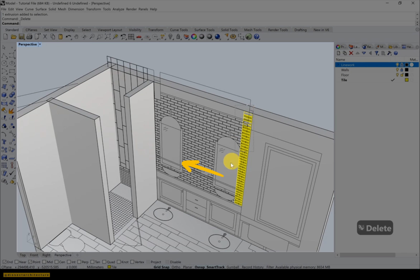
Step 13
After trying out a tile layout, I decided to change it and created a column of tiles and then grouped them together.
Then I used the Array command to distribute them along the wall and deleted any extra tiles. After I was done adding the tiles I adjusted them back to their original color.
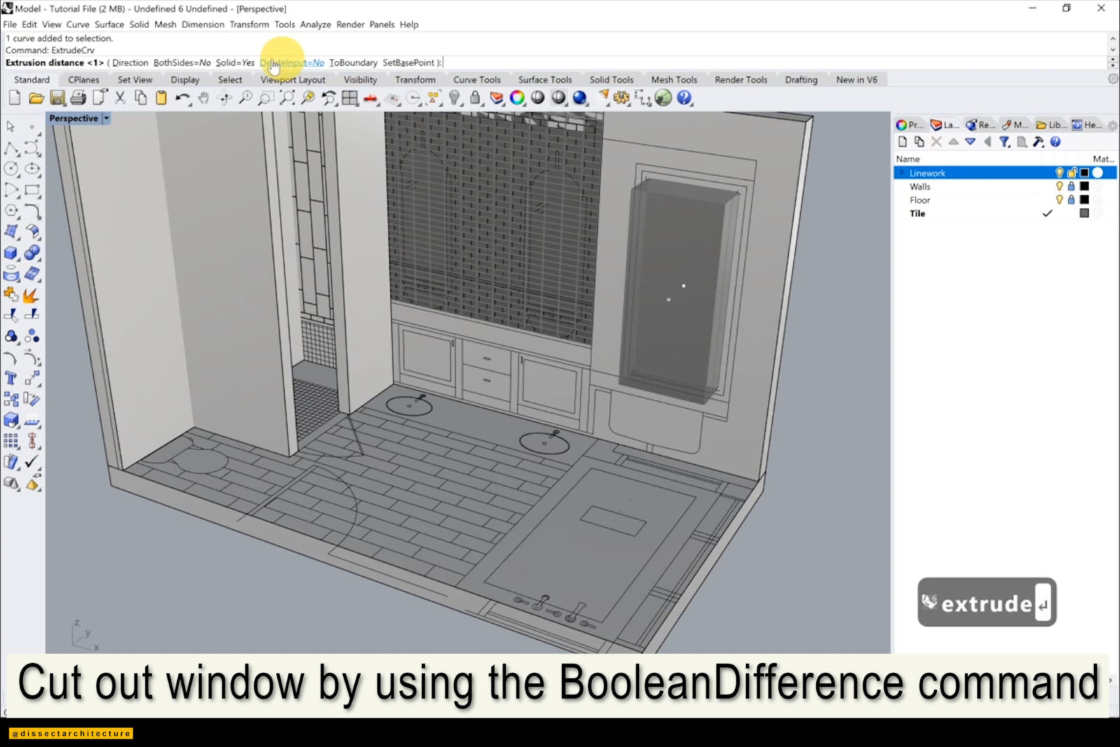
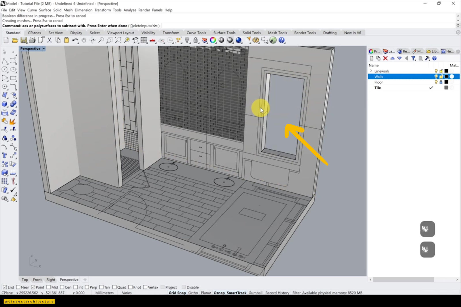
Step 14
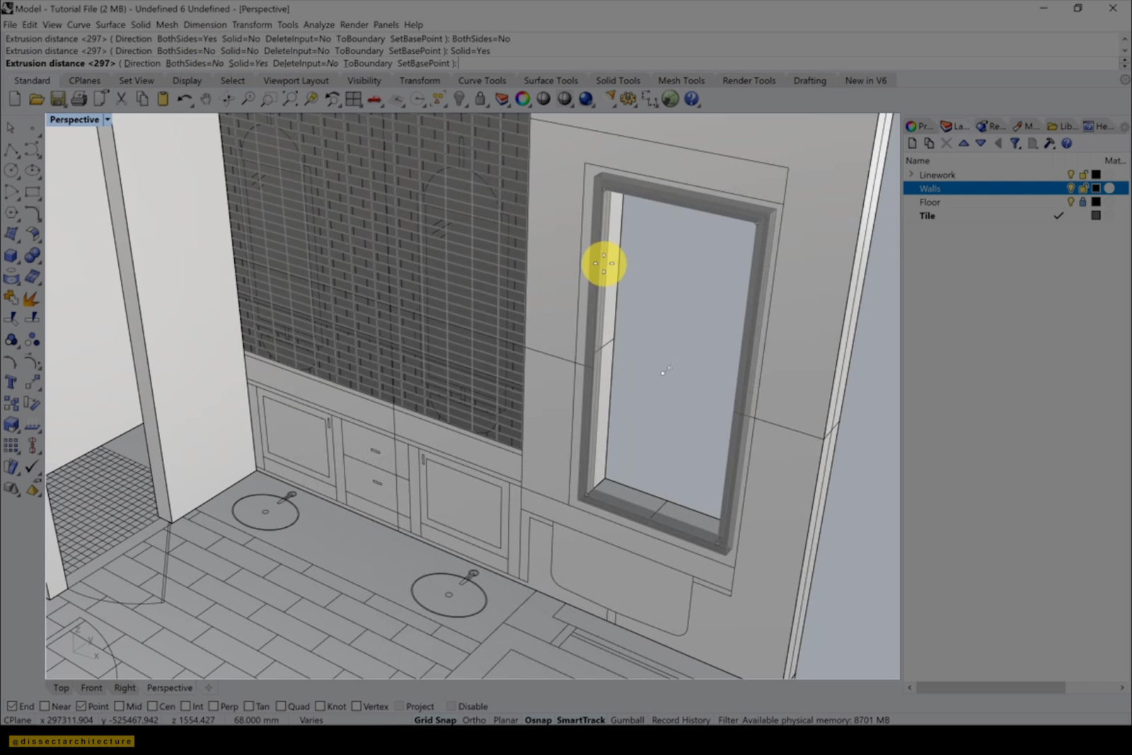
Use the BooleanDifference command and elevation linework to cut out any windows through the wall.
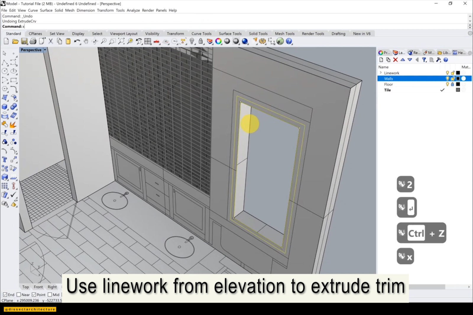
Step 15
After you are done, use the Extrude command and the linework from the elevation to create a trim around the window.
Make sure to place each modeled element in its own layer.
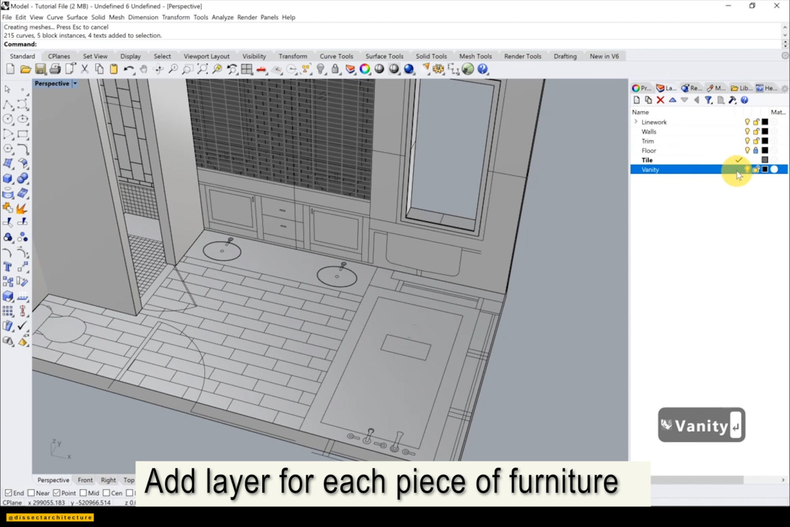
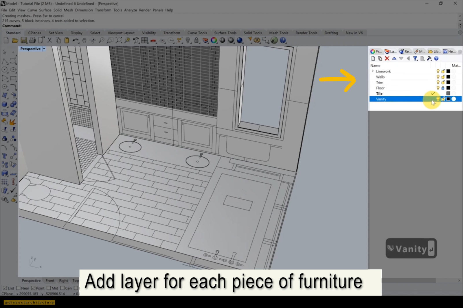
Step 16
Now let’s begin to place the bathroom fixtures!
I am first modeling the vanity with the Box command.
Step 17
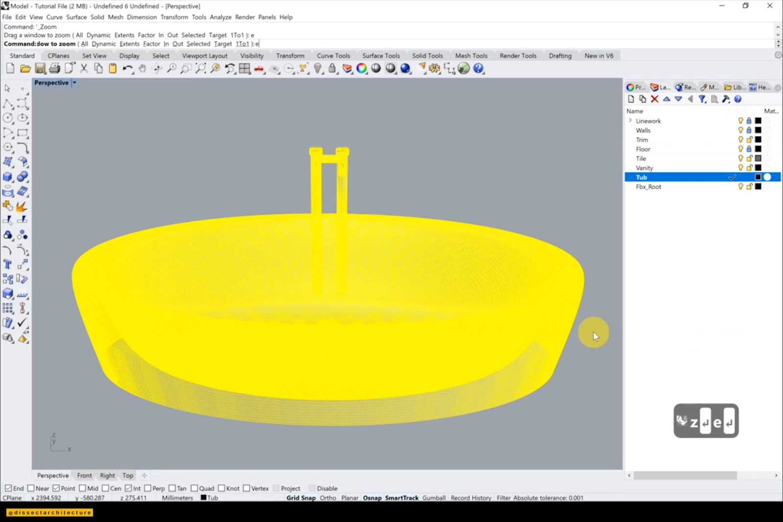
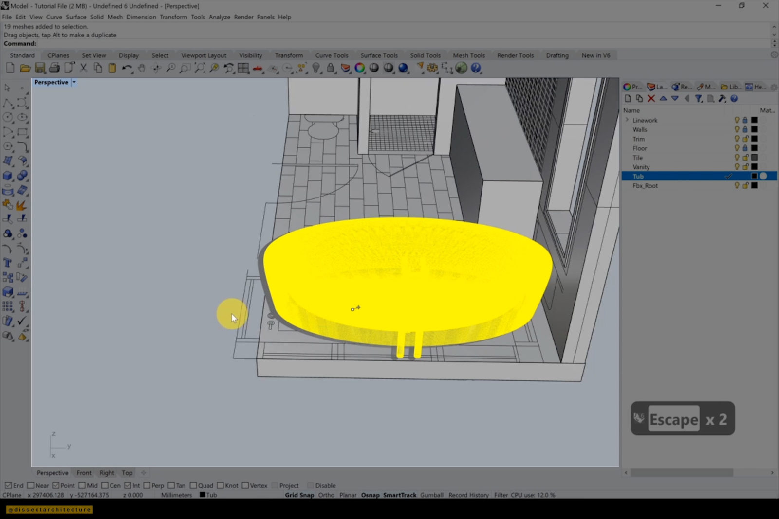
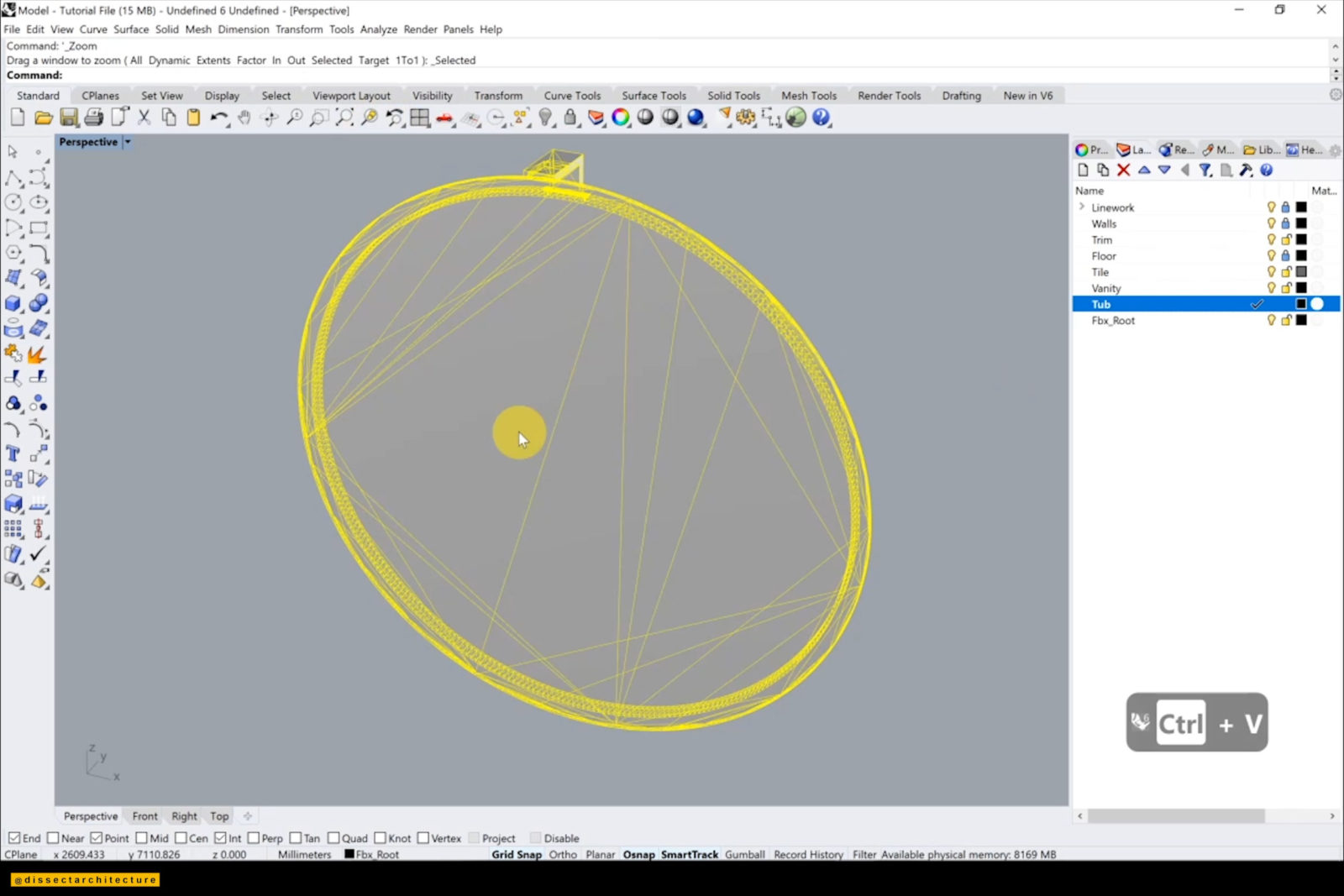
I then pasted in a 3D model of a tub. You can find various free 3D model resources online such as TurboSquid.
Use the Rotate command to place the tub accordingly with the plan and scale it down to fit the scale of the room with the Scale and Scale1D command.
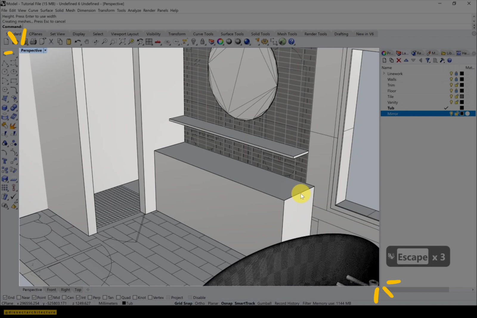
Step 18
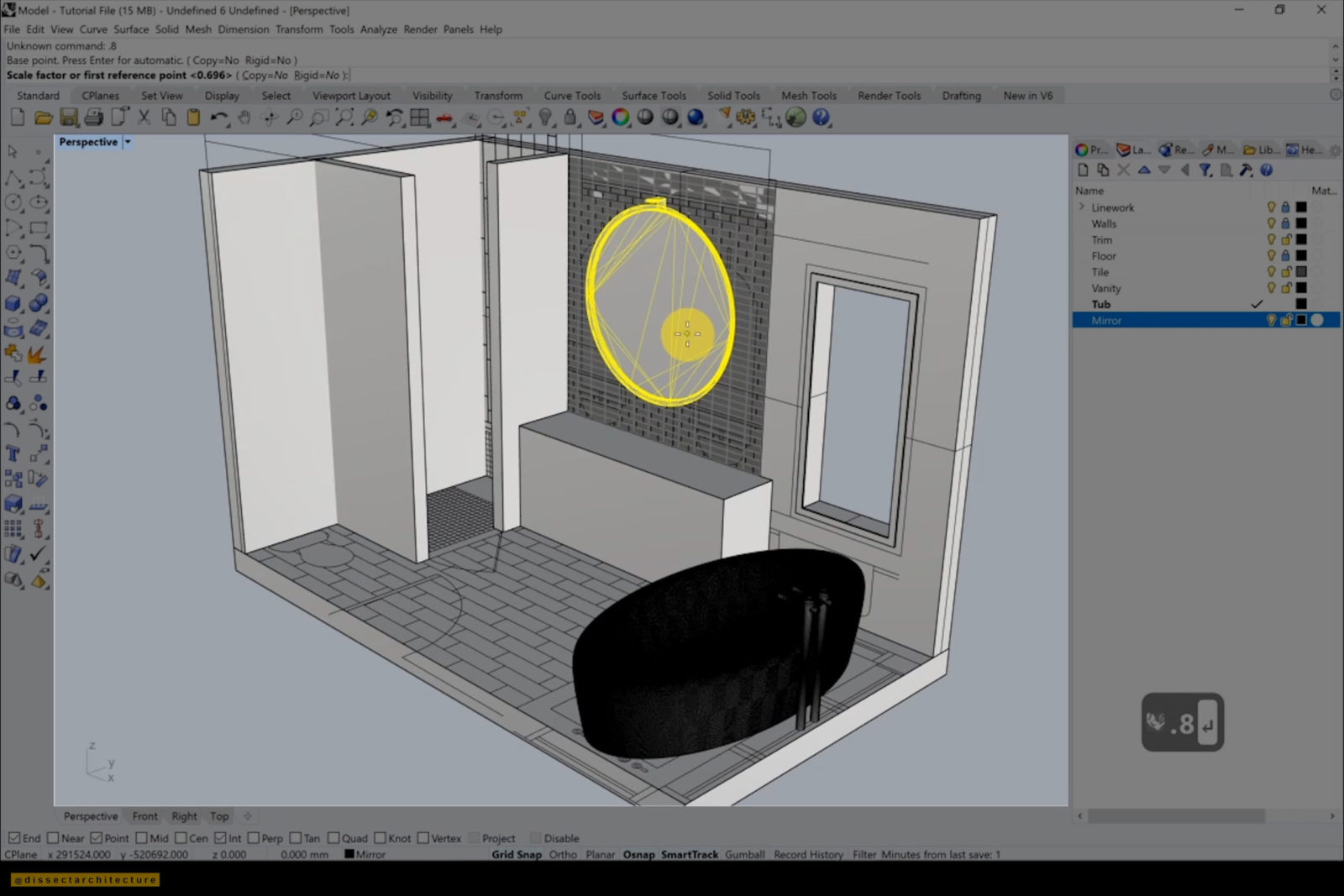
Next I added a circular 3D mirror and transformed it with the Scale command to fit the room.
Step 19
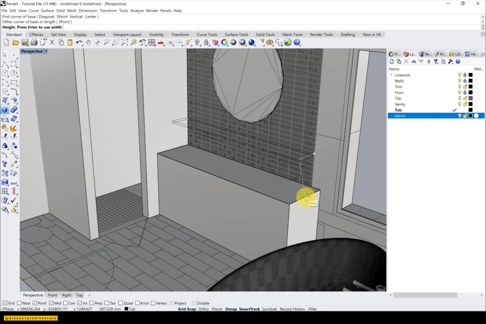
I am adding a shelf beneath the mirror by extruding linework from the elevation by using the Extrude command.
Make any adjustments if needed.
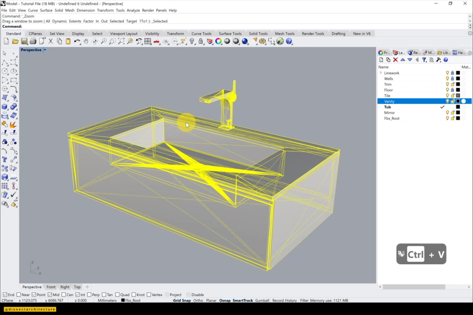
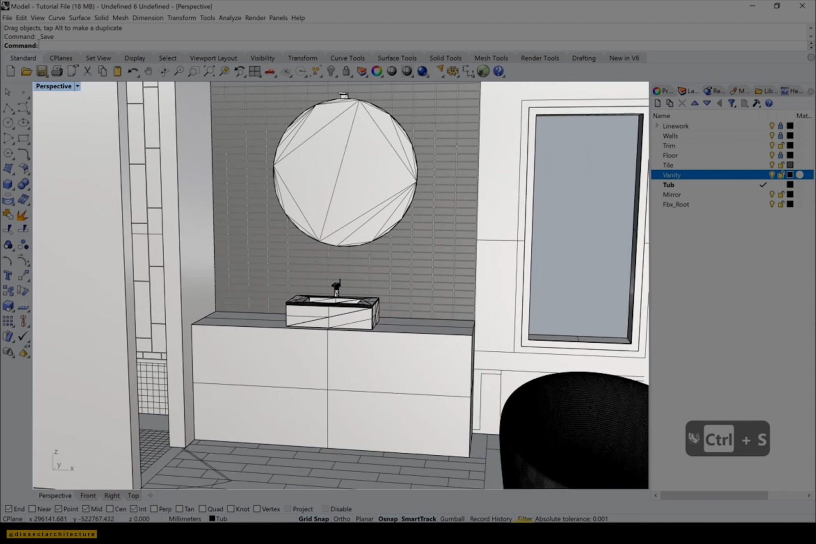
Step 20
Continue to add fixtures – I have added a sink. Scale it down and since the sink was a mesh I used the MeshtoNurb command to turn it into polysurfaces. I then placed it over the vanity.
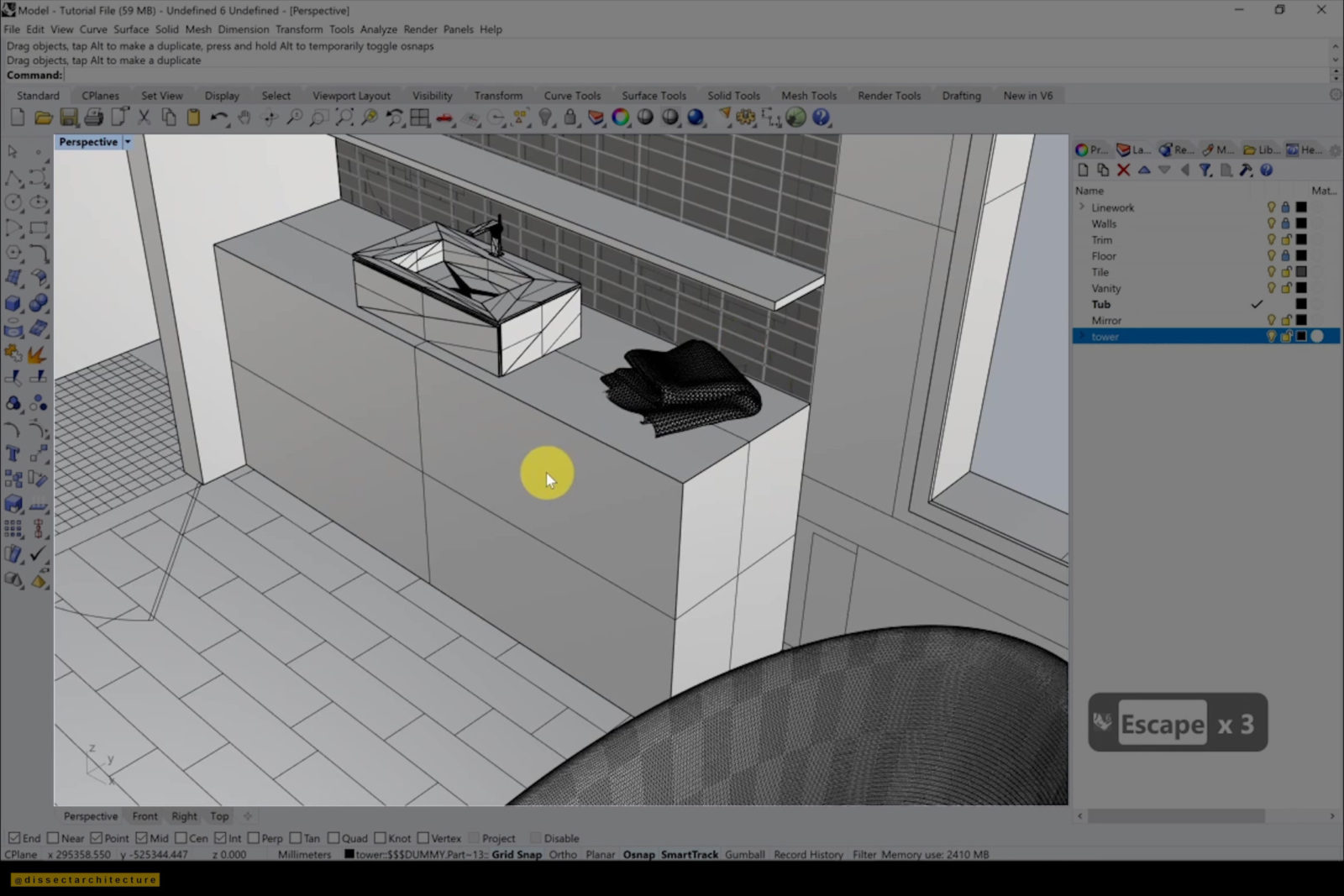
Step 21
Make sure to also add accessories to the room. The accessory I added was a towel. I scaled it down and used the MeshtoNurb command to turn the mesh into polysurfaces. I am placing it atop of to the vanity, next to the sink using the Move command.

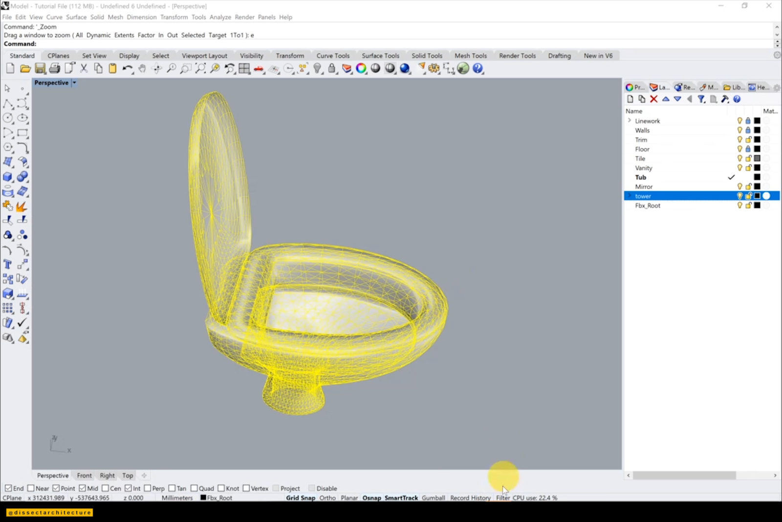
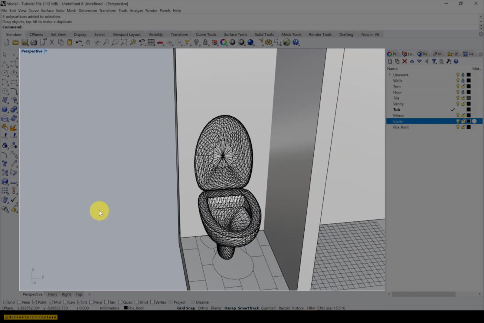
Step 22
Later, I added a toilet as well by using the previous techniques to add it to the location it belongs.
I used the MeshtoNurbs command to transform the meshes and grouped all the surfaces of the toilet with the Group command.
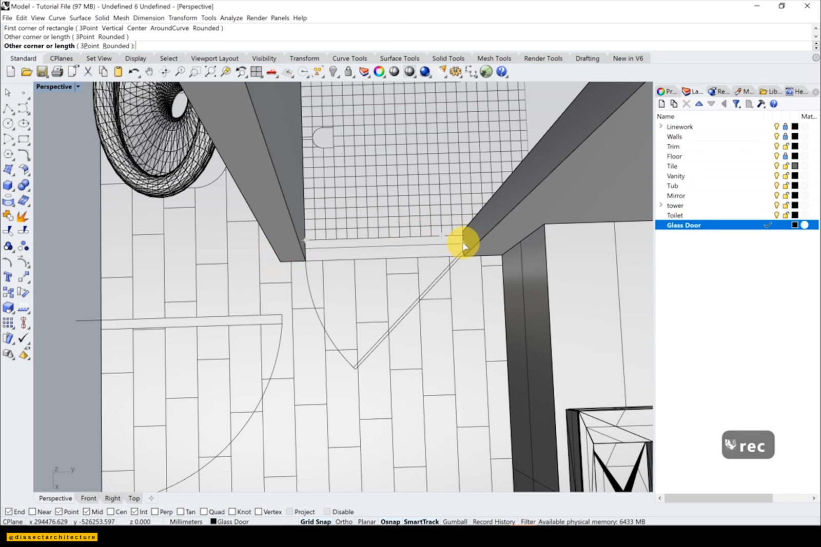
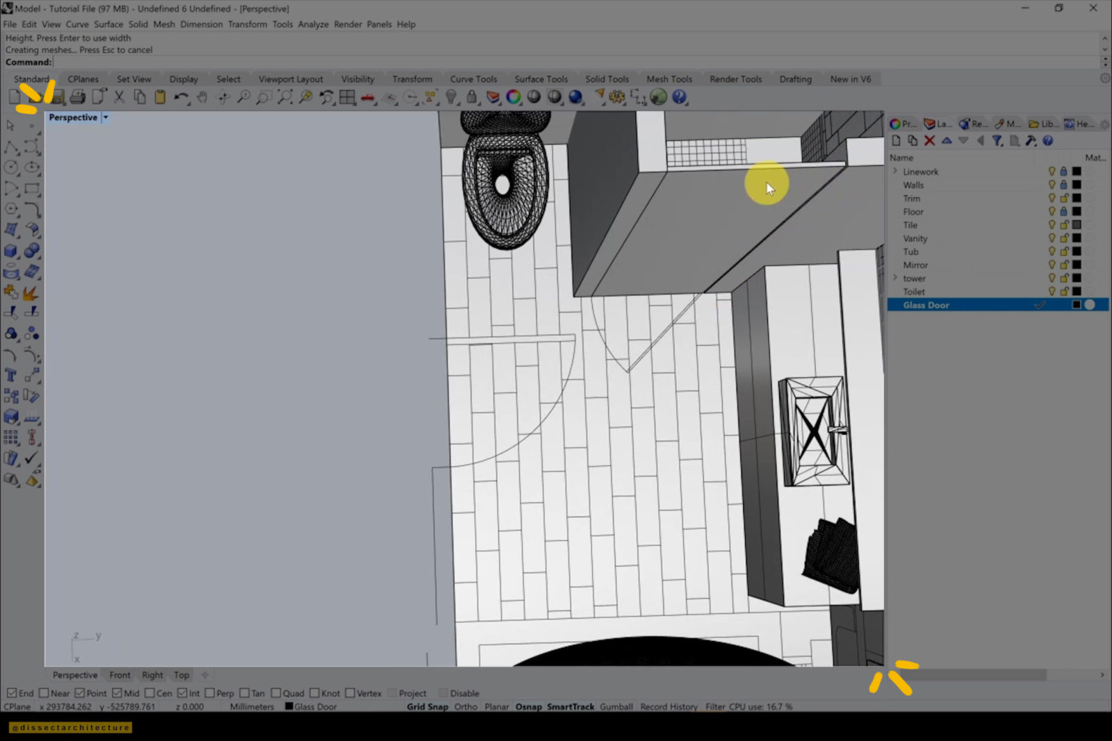
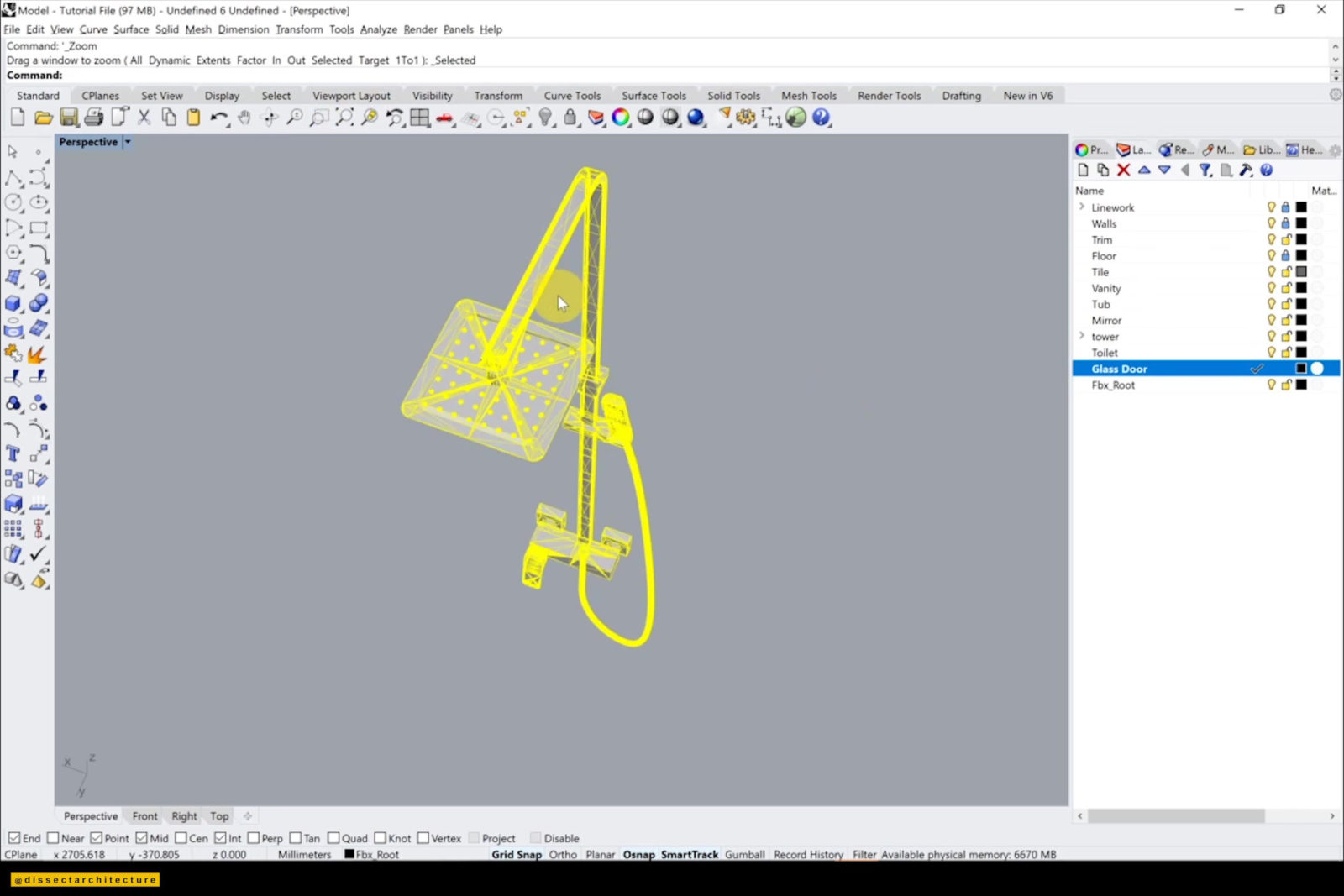
Step 23
Afterwards, I am adding a thin glass shower door in its own individual layer using the Box command.
Step 24
Afterwards I added a shower head and placed it on its location by using the plan as reference.
Double-check to see if there is anything else to add to your model.
Make sure to save your work!
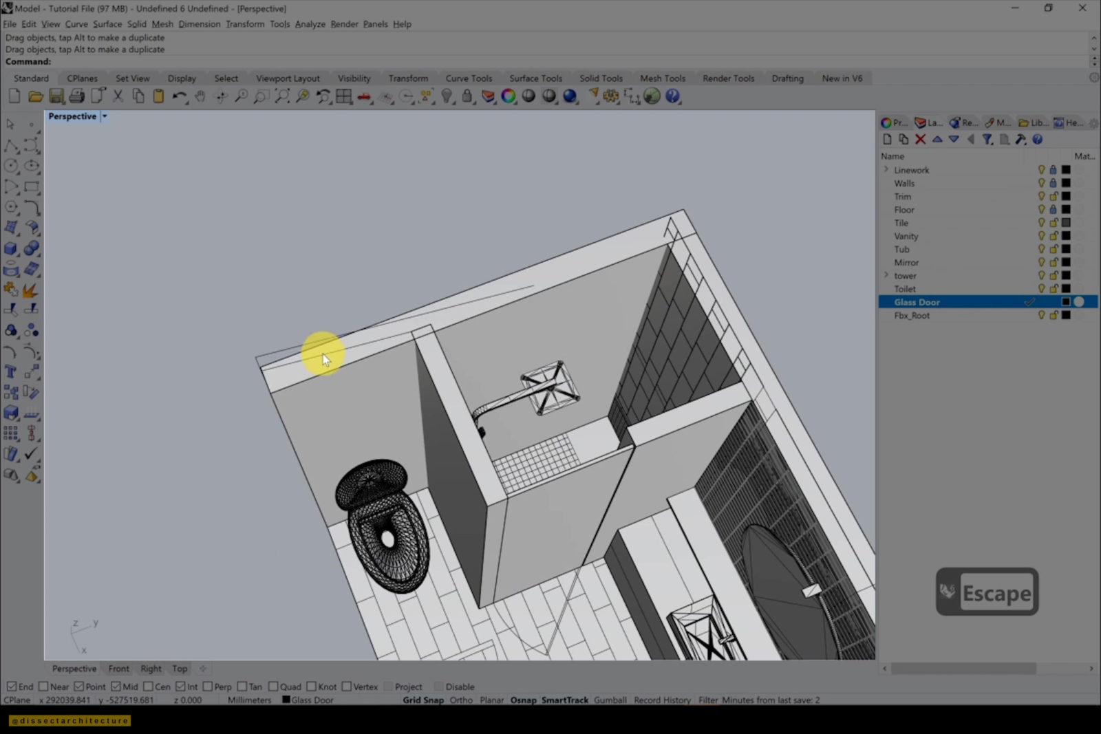
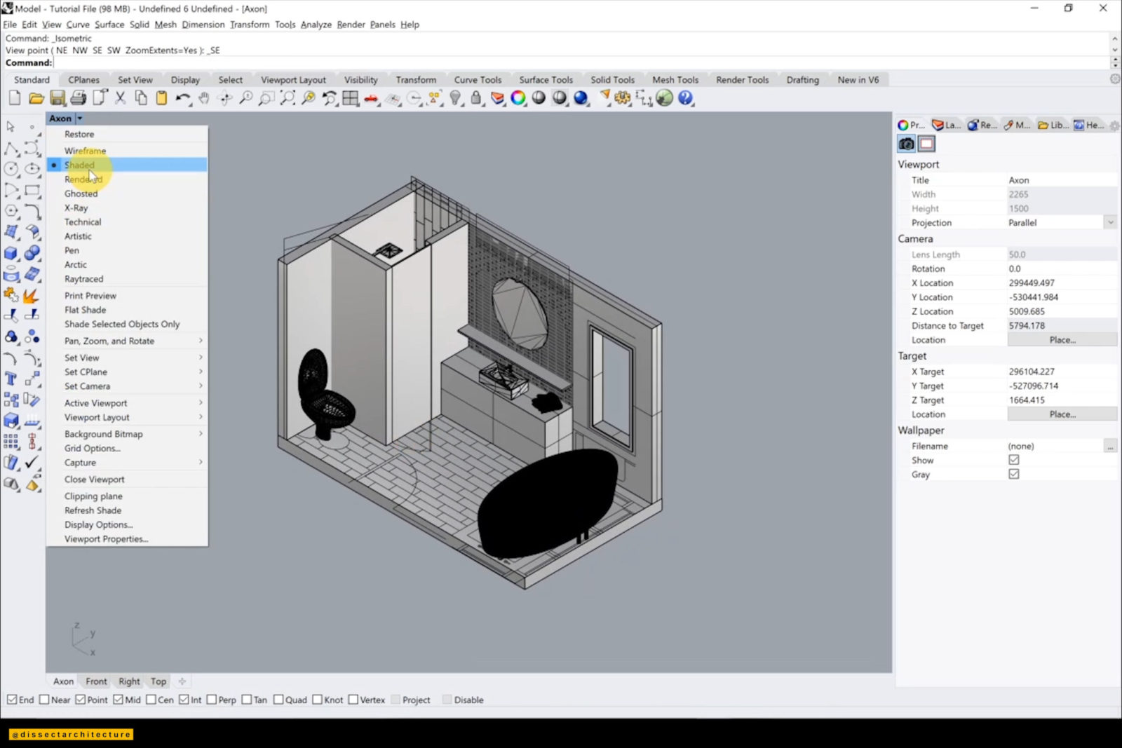
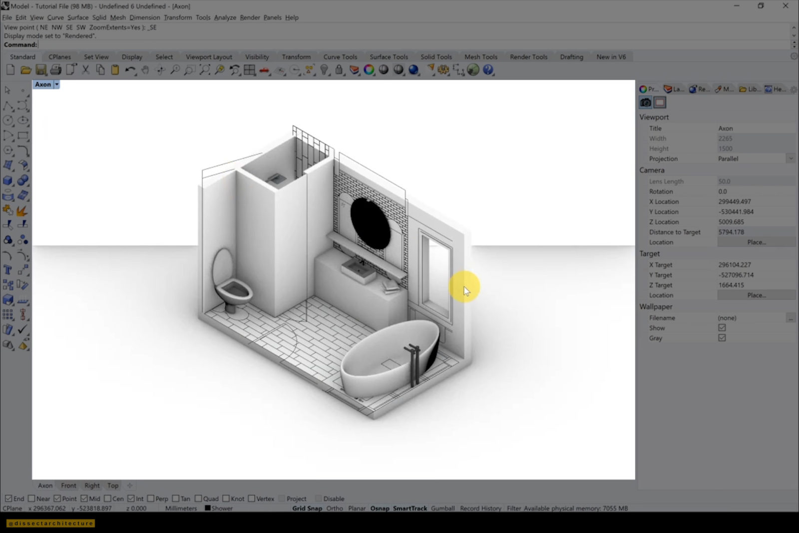
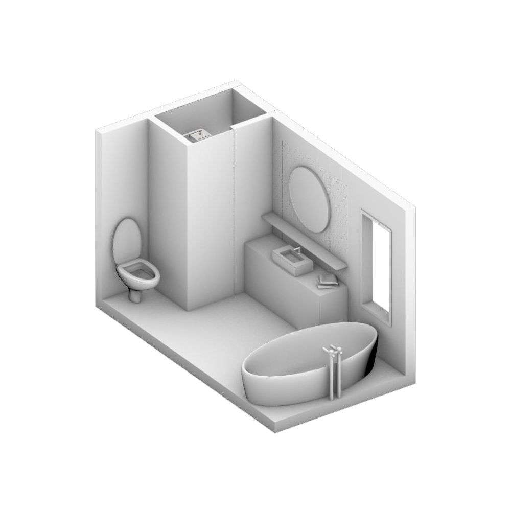
Step 25
Lastly, set your view to your desired isometric view and then switch the viewport display to render to see a cleaner view of the model.
You now understand how to model an axon in Rhino!